
Method for optimizing radio frequency pulses in fast spin echo pulse sequence

A technology of spin echo and pulse sequence, which is applied in the fields of magnetic variable measurement, nuclear magnetic resonance imaging system measurement, magnetic resonance measurement, etc., can solve the problems that the synthetic signal cannot obtain the optimal result and the optimization result is not ideal, and achieves Effects of reducing influence, improving optimization efficiency, and meeting the needs of magnetic resonance imaging

Active Publication Date: 2019-04-30
康达洲际医疗器械有限公司
View PDF6 Cites 5 Cited by
  • Summary
  • Abstract
  • Description
  • Claims
  • Application Information

AI Technical Summary

Problems solved by technology

Therefore, using the above scheme to adjust the composite signal of the two sometimes cannot obtain the optimal result, especially in the high-field magnetic resonance imaging system, the radio frequency field non-uniformity is more significant, and the optimization results of the above scheme are often not ideal

Method used

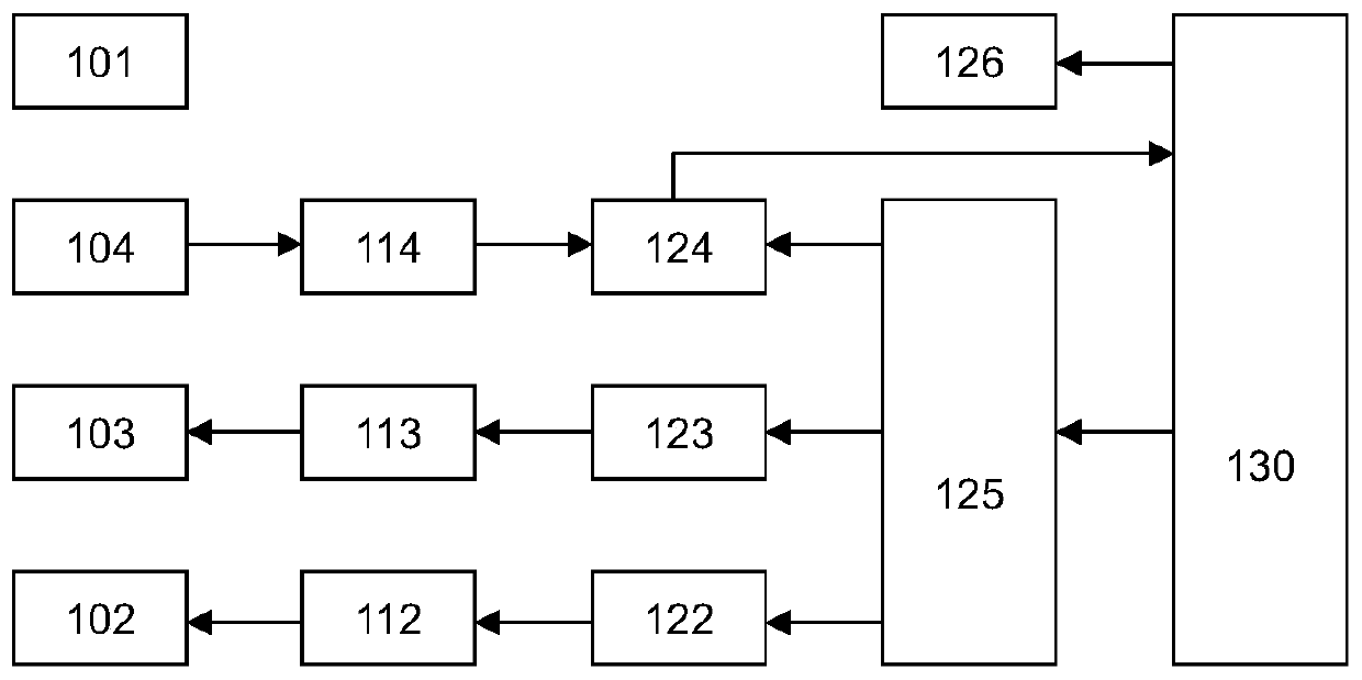

Image

  • Method for optimizing radio frequency pulses in fast spin echo pulse sequence
  • Method for optimizing radio frequency pulses in fast spin echo pulse sequence
  • Method for optimizing radio frequency pulses in fast spin echo pulse sequence

Examples


Embodiment 1

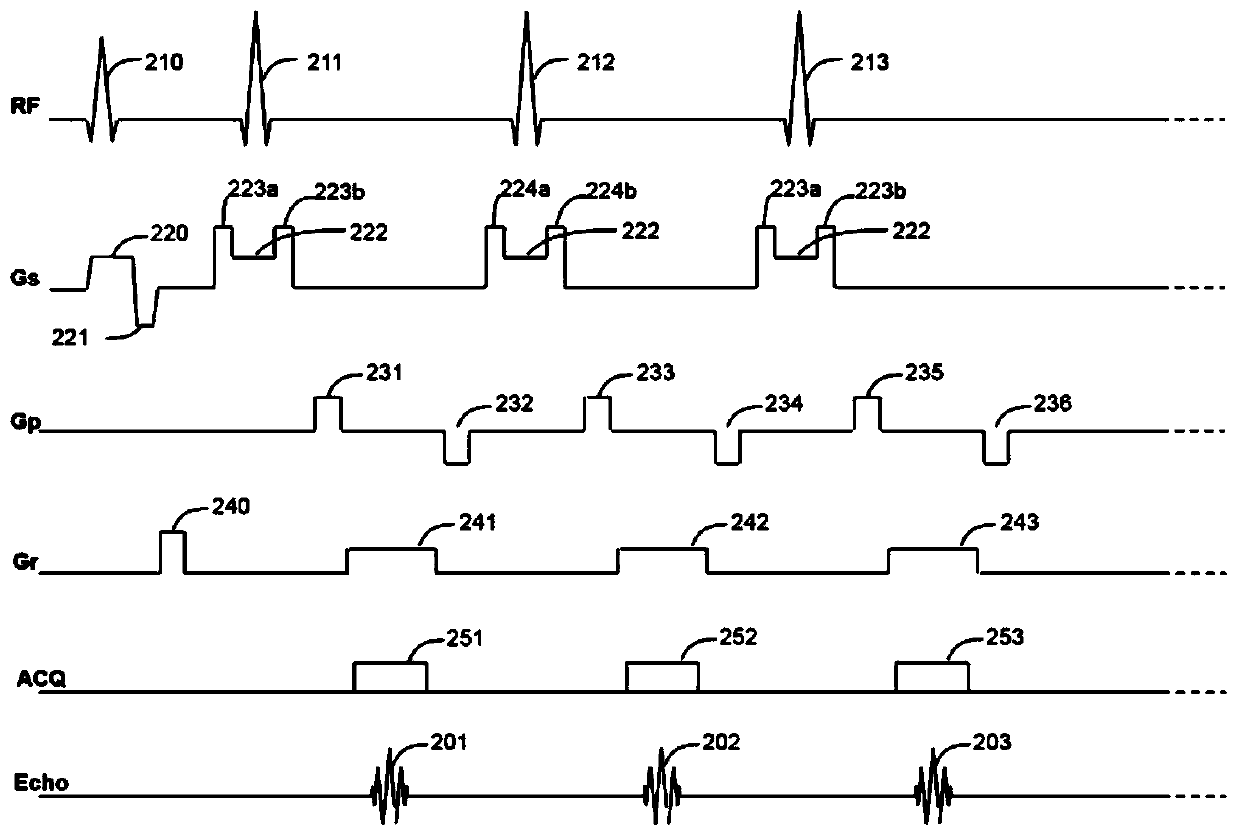
[0041] refer to figure 2 and image 3 , the method for optimizing radio frequency pulses in the fast spin echo pulse sequence provided by the present invention comprises the following specific steps:

[0042] a) Set the amplitudes of "phase encoding gradients" 231, 232, 233, 234, 235, and 236 to 0; the excitation pulse 210 uses π / 2 pulses, and the phase of the excitation pulse is set to 0; the inversion pulses 211, 212, and 213 are all With π pulses, the inverted pulse phases are all set to The amplitudes of two adjacent groups of "spoiler gradients" are set to unequal values, and the amplitudes of a pair of "spoiler gradients" in the same group are equal, that is, setting (223a=223b)≠(224a=224b);

[0043] b) Adjust the starting time of the "readout gradient" 241, 242 and 243, so that the peak points of the echo signals 201, 202 and 203 on the echo chain are located in the middle of the sampling window. If the time difference between the peak point of 202 and the center o...

Embodiment 2

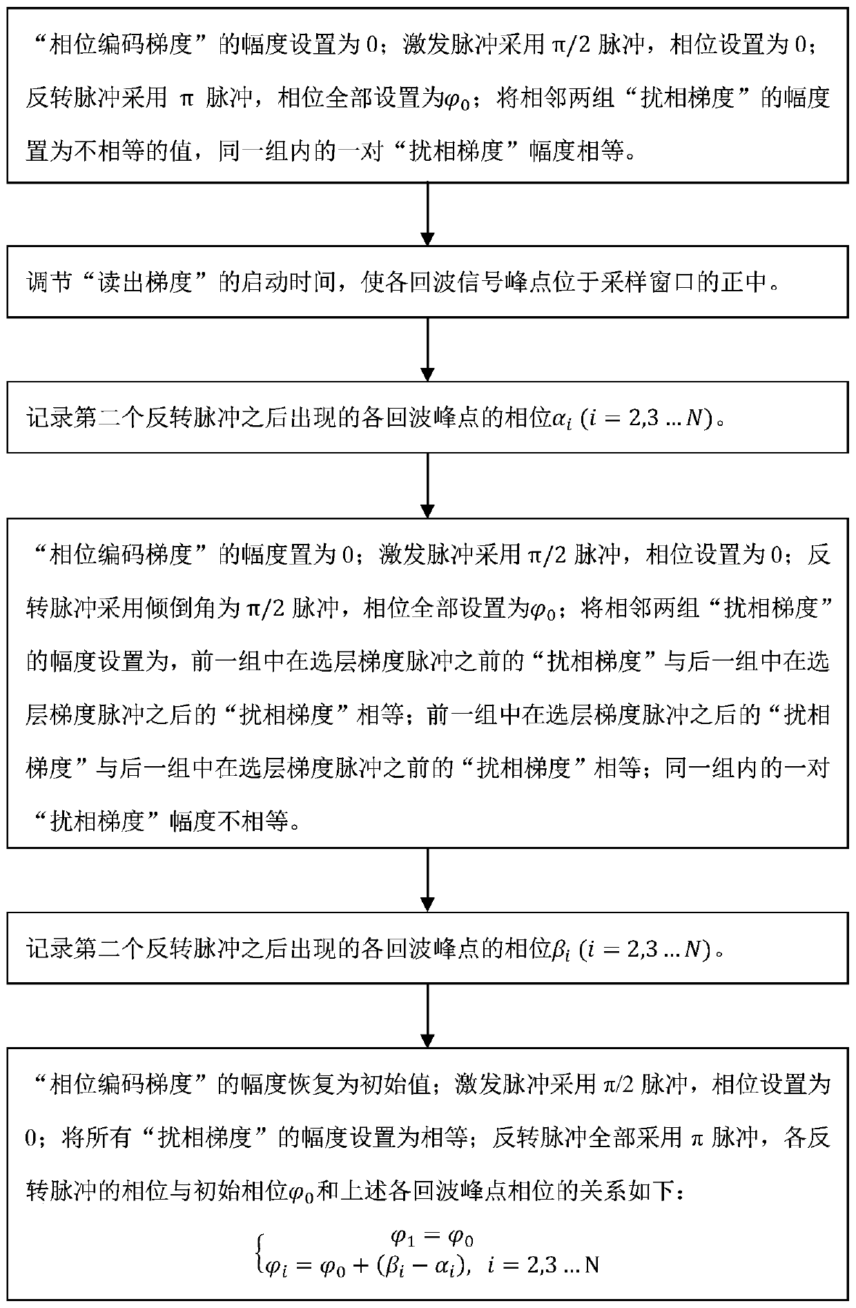
[0052] refer to figure 2 and Figure 4 , the method for optimizing radio frequency pulses in the fast spin echo pulse sequence provided by the present invention comprises the following specific steps:

[0053] a) Set the amplitudes of "phase encoding gradients" 231, 232, 233, 234, 235, and 236 to 0; the excitation pulse 210 uses π / 2 pulses, and the phase of the excitation pulse is set to 0; the inversion pulses 211, 212, and 213 are all With π / 2 pulses, the reverse pulse phases are all set to Set the amplitude of the adjacent two groups of "spoiler gradients" so that the "spoiler gradient" before the layer selection gradient pulse in the previous group is equal to the "spoiler gradient" after the layer selection gradient pulse in the latter group, The "spoiler gradient" after the layer selection gradient pulse in the previous group is equal to the "spoiler gradient" before the layer selection gradient pulse in the latter group; the amplitude of a pair of "spoiler gradients...


PUM


Abstract

The invention provides a method for optimizing radio frequency pulses in a fast spin echo pulse sequence. According to the method, spin echoes and stimulated echoes are separated by utilizing the difference of the action of a disturbed phase gradient on the spin echoes and the stimulated echoes, and the stimulated echoes or the spin echoes disappear through reverse pulses with different tilt angles, so that independent adjustment of the spin echoes and the stimulated echoes is realized; and the phase of the reverse pulse is optimized by using the relationship among the spin echoes, stimulatedechoes and reverse pulses in phase. According to the method, the influence of radio frequency field heterogeneity on the FSE sequence parameter optimization process can be reduced, the radio frequencypulse optimization efficiency is improved, and the method is particularly suitable for a high-field magnetic resonance imaging system.

Description

technical field [0001] The invention belongs to the technical field of magnetic resonance imaging, and relates to a method for optimizing radio frequency pulses in a fast spin echo pulse sequence. Background technique [0002] Magnetic resonance imaging (MRI) technology has become a very useful tool in medical diagnosis. Usually, in an MRI instrument, when the sample to be tested (such as human tissue) is placed in a static magnetic field B 0 (B 0 The direction is defined as the Z-axis direction of the Cartesian coordinate system) when equilibrium is reached, the atomic nuclei (nuclear spins) in the sample are affected by the B 0 Polarized to produce a macroscopic magnetization vector M 0 ; the M 0 Under the excitation of radio frequency pulses, it is rotated to the horizontal plane (XY plane), and then precesses around the Z axis. A receiving coil is placed around the tested sample, and it will induce the precession signal of the magnetization vector. After the magnet...

Claims


Application Information

Patent Timeline
IPC IPC(8): G01R33/54G01R33/56
CPCG01R33/54G01R33/56
Inventor 宁瑞鹏杨光谢海滨淡一波易音巧刘绅
Owner 康达洲际医疗器械有限公司
Learn More