
Nanomaterial production device based on LICVD method

A technology of nanomaterials and production equipment, applied in chemical instruments and methods, chemical/physical/physicochemical processes using energy, chemical/physical/physicochemical processes, etc. The vacuum is not complete, the reaction environment is not clean enough, etc., to achieve the effects of reducing production costs, flexible structure, and convenient operation

Active Publication Date: 2019-04-30
苏州邦得绿建科技有限公司
View PDF12 Cites 0 Cited by
  • Summary
  • Abstract
  • Description
  • Claims
  • Application Information

AI Technical Summary

Problems solved by technology

[0003] When the existing production equipment uses the LICVD method to prepare nanomaterials, it is necessary to do a good job of purifying the reaction chamber, that is, to prepare for vacuuming, and to fill in high-purity inert protective gas at the same time, so as to ensure the reaction in a clean environment, but In the actual operation process, the vacuum of the reaction chamber is often incomplete. In addition to the inert gas, the reaction chamber also contains other gases, which makes the reaction environment not clean enough and affects the progress of the reaction. Not only that, when preparing nanopowder, the reaction There are many kinds of gases. Before the gas molecules collide with each other, each gas molecule that participates in the reaction absorbs laser energy, which causes decomposition. Because the equipment is difficult to adjust the proportion of various gases, too little gas will easily lead to insufficient reaction. Too much gas will easily cause waste of generated materials, further reducing the practicability of existing LICVD reaction devices

Method used


Image

  • Nanomaterial production device based on LICVD method
  • Nanomaterial production device based on LICVD method
  • Nanomaterial production device based on LICVD method

Examples


Embodiment Construction

[0024] The present invention is described in further detail now in conjunction with accompanying drawing. These drawings are all simplified schematic diagrams, which only illustrate the basic structure of the present invention in a schematic manner, so they only show the configurations related to the present invention.

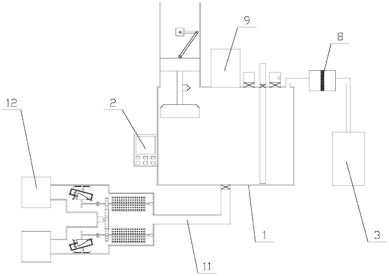
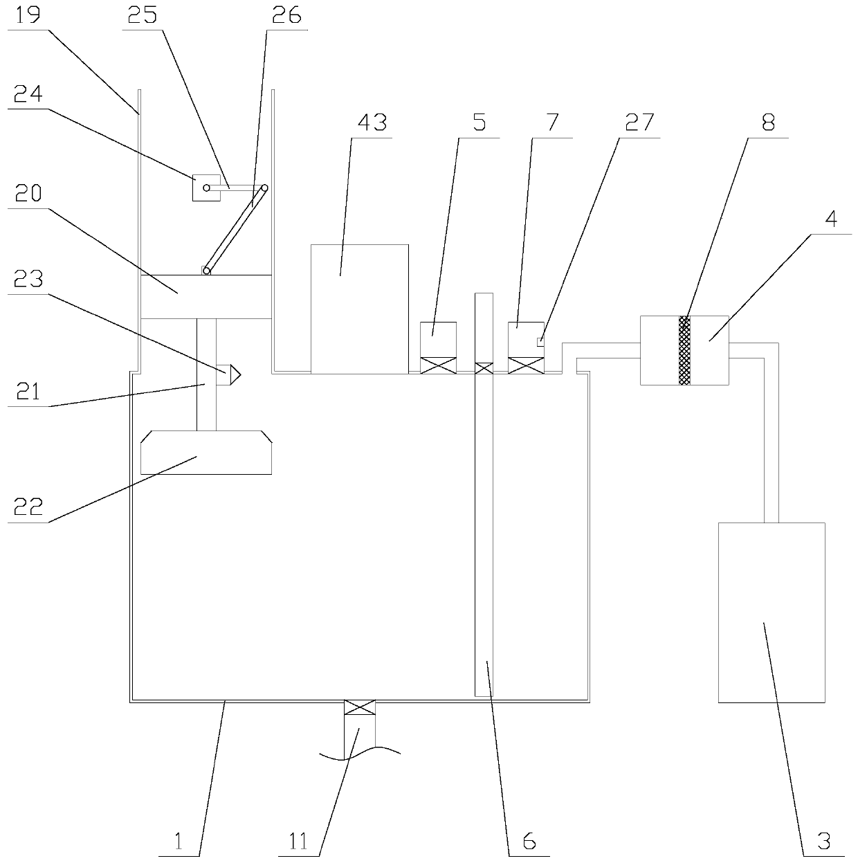
[0025] Such as figure 1 As shown, a nano-material production equipment based on LICVD method includes a reaction chamber 1, a controller 2, a gas supply mechanism, a cleaning mechanism, a trap 9 and an irradiation mechanism, and the controller 2 is fixed on a part of the reaction chamber 1. side, the gas supply mechanism is connected to the bottom of the reaction chamber 1, the irradiation mechanism is arranged above the reaction chamber 1, the trap 9 is fixed above the reaction chamber 1, and the cleaning mechanism is connected to the reaction chamber 1 , the controller 2 is provided with a PLC, and the trap 9 is electrically connected to the PLC;

[0026] ...


PUM


Abstract

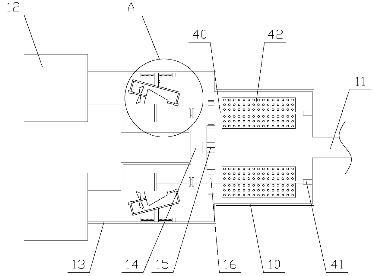
The invention relates to a nanomaterial production device based on an LICVD method, wherein the nanomaterial production device includes a reaction chamber, a controller, a gas supply mechanism, a cleaning mechanism, a trapper and an irradiation mechanism. The cleaning mechanism includes an inert gas chamber, a heating box, a water injection pipe, a drainage pipe and an exhaust pipe. The gas supplymechanism includes a mixing pipe, a mixing chamber and a plurality of gas supply assemblies. The gas supply assemblies each include a gas supply chamber and a gas supply pipe. A first motor and a first gear are arranged in the mixing chamber; an adjusting assembly is arranged in each gas supply pipe and includes a second gear, a rotating shaft, a rotating disk and a gas supply unit. The nanomaterial production device based on the LICVD method cleans the interior of the reaction chamber through the cleaning mechanism, the reaction chamber is full of inert gas, a clean reaction environment is ensured and the production of the nanomaterial is facilitated. Moreover, the gas supply mechanism provides a specific proportion of various gases to the reaction chamber, the full reaction of various reaction gases is facilitated, gas waste is prevented, the production costs are reduced and the practicability of the device is improved.

Description

technical field [0001] The invention relates to the field of new material equipment, in particular to a nano material production equipment based on LICVD method. Background technique [0002] The full name of LICVD is Laser-Induced Chemical Vapor Deposition. It is a synthetic nano-powder technology that uses laser as a heating source and induces a gas phase reaction in the late 1970s. Its main principle is to use the reaction gas molecules to absorb specific wavelength laser beams. Laser photolysis, laser pyrolysis, laser photosensitization, and laser-induced chemical synthesis reactions are caused to react gas molecules. Under certain process conditions, ultrafine particles are obtained to grow nuclei and grow in space. At present, LICVD method has prepared a variety of single species, Ultrafine powders of inorganic compounds and composite materials, the main products produced are nano-silicon-based powders and extremely nano-oxide powders. [0003] When the existing produ...

Claims


Application Information

Patent Timeline
Patent Type & Authority Applications(China)
IPC IPC(8): B01J19/12
CPCB01J19/0053B01J19/121
Inventor 曹燕红
Owner 苏州邦得绿建科技有限公司
Learn More