
Switch device and electric tool with same

A switch device and circuit board technology, which is applied in the direction of electronic switches, electrical components assembly printed circuit, electrical components, etc., can solve the problems of high cost, complicated assembly process, complex structure of switch device, etc., and achieve simplified structure and assembly process, The effect of reducing production costs

Pending Publication Date: 2019-04-26
SHANGHAI BAICHENG ELECTRONICS
View PDF0 Cites 0 Cited by
  • Summary
  • Abstract
  • Description
  • Claims
  • Application Information

AI Technical Summary

Problems solved by technology

[0003] The main purpose of the present invention is to provide a switchgear and an electric tool with it, so as to solve the problems of complex structure, complicated assembly process and high cost of the switchgear in the prior art

Method used


Image

  • Switch device and electric tool with same
  • Switch device and electric tool with same
  • Switch device and electric tool with same

Examples


Embodiment Construction

[0032] It should be noted that, in the case of no conflict, the embodiments in the present application and the features in the embodiments can be combined with each other. The present invention will be described in detail below with reference to the accompanying drawings and examples.

[0033] It should be pointed out that the following detailed description is exemplary and intended to provide further explanation to the present application. Unless defined otherwise, all technical and scientific terms used herein have the same meaning as commonly understood by one of ordinary skill in the art to which this application belongs.

[0034] The following will clearly and completely describe the technical solutions in the embodiments of the present invention with reference to the accompanying drawings in the embodiments of the present invention. Obviously, the described embodiments are only some, not all, embodiments of the present invention. The following description of at least on...


PUM


Abstract

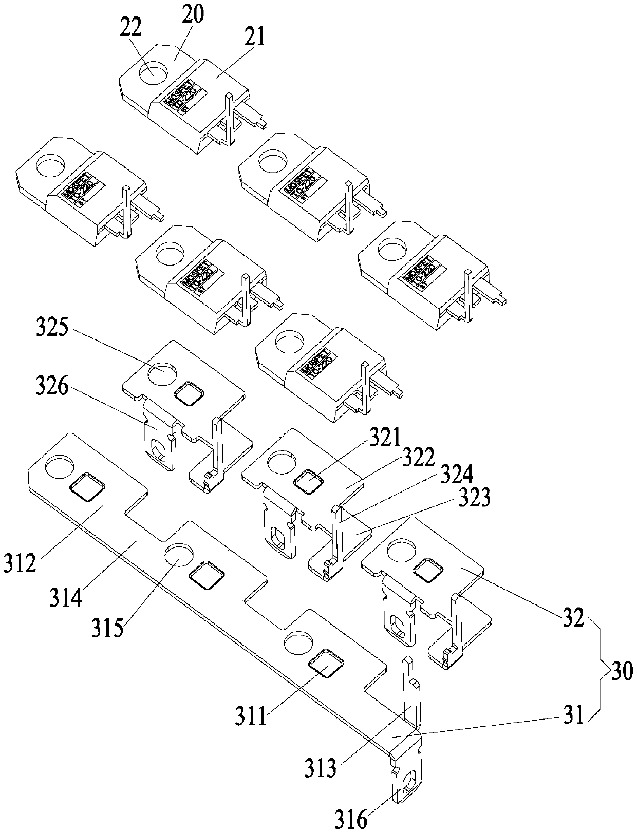
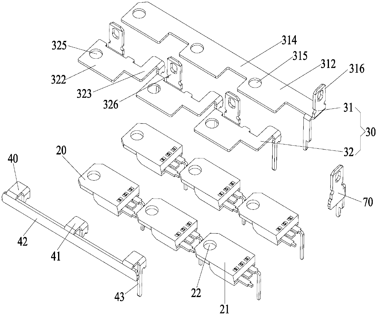
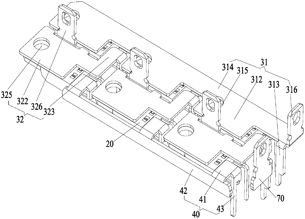
The invention provides a switch device and an electric tool with the same. The switch device comprises a circuit board, an MOS tube connected with the circuit board and comprising a radiating body andan electrode D connected with the radiating body, an electrode D connecting structure, wherein the radiating body is electrically connected with the electrode D of the MOS tube, and the electrode D connecting structure is connected with the radiating body and the circuit board so as to connect the electrode D of the MOS tube with the circuit board. The problem can be solved that a switch device in the prior art is complex in structure, complex in assembly process and high in cost.

Description

technical field [0001] The invention relates to the field of tools, in particular to a switch device and an electric tool with the same. Background technique [0002] Currently, there are two commonly used brushless switch devices for electric tools on the market, one is a separate switch device and the other is an integrated switch device. For the separate switchgear, the control module of the motor is arranged outside the switchgear, which is cumbersome to install and the installation efficiency is low, while the control module of the motor is set inside the switchgear for the integrated switchgear. Although the integrated switch device can solve the problem of low installation efficiency, due to the limited installation space, an additional heat sink is required to dissipate heat from the MOS tube, resulting in a complex structure of the switch device, complicated assembly process, and high cost. Contents of the invention [0003] The main purpose of the present invent...

Claims


Application Information

Patent Timeline
IPC IPC(8): H05K7/20H05K3/32H03K17/687
CPCH03K17/687H05K3/32H05K7/2039
Inventor 谭和平
Owner SHANGHAI BAICHENG ELECTRONICS
Learn More