
Self-adjusting multiphase pump

A mixed pump and self-adjusting technology, applied in the field of self-adjusting mixed pump, can solve the problems of inability to form a vacuum, cut-off, and inability to absorb the medium.

Inactive Publication Date: 2019-04-26
DALIAN LEO HUANENG PUMP
View PDF6 Cites 1 Cited by
  • Summary
  • Abstract
  • Description
  • Claims
  • Application Information

AI Technical Summary

Problems solved by technology

[0005] According to the above proposal, when transporting the medium with high gas content, the existing centrifugal pump has the technical problem of gas accumulation at the impeller inlet due to the small gas centrifugal force, which cannot form a vacuum, and the medium cannot be sucked up and the flow is cut off. Adjustable mixing pump

Method used


Image

  • Self-adjusting multiphase pump
  • Self-adjusting multiphase pump

Examples


specific Embodiment 1

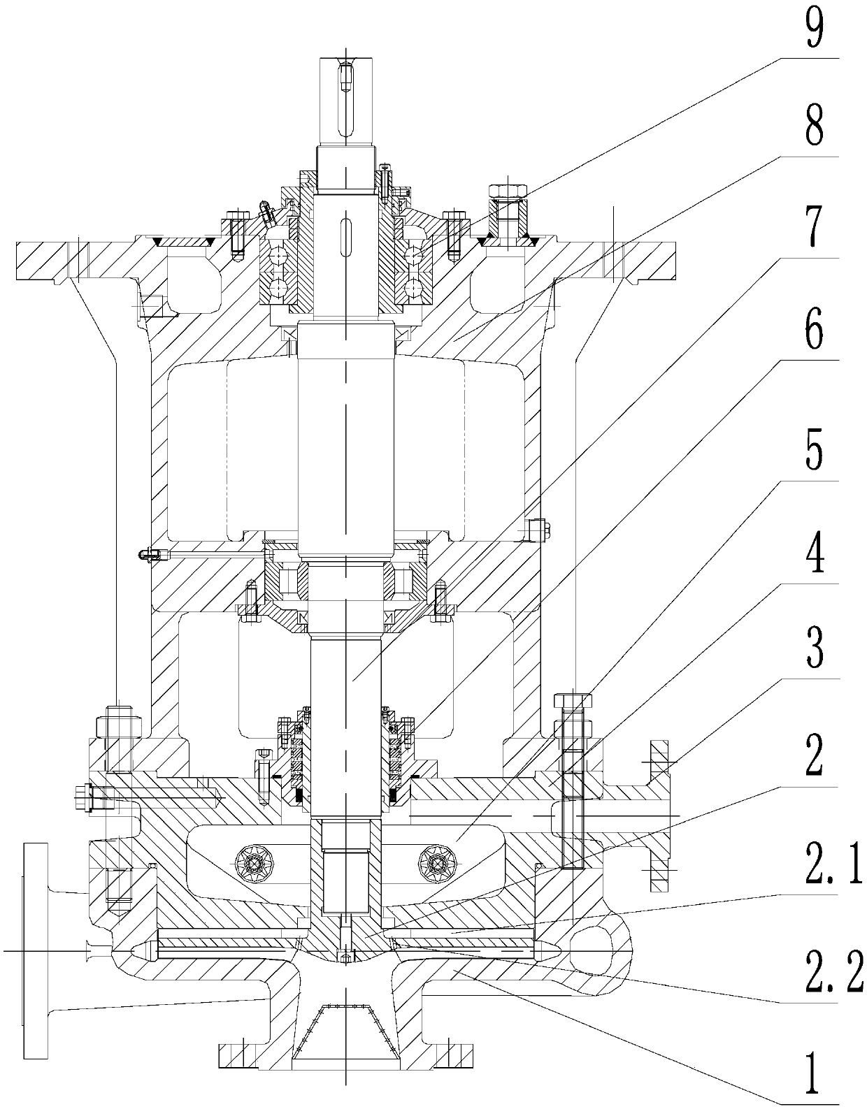
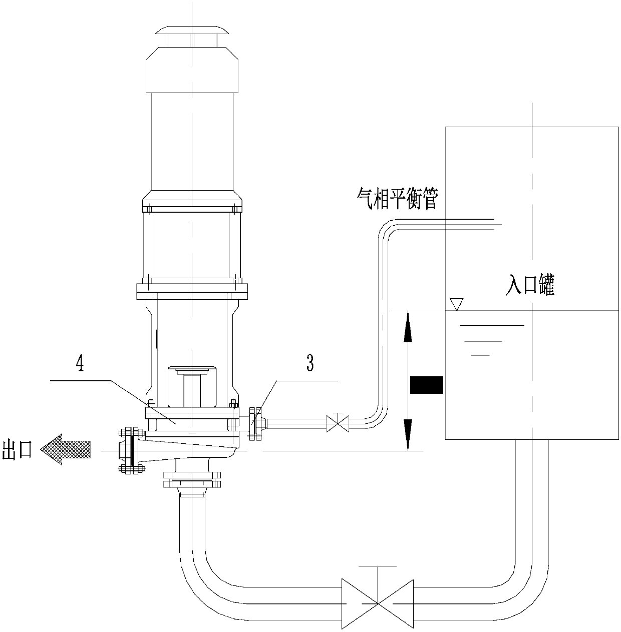
[0029] As shown in the figure, the present invention provides a self-adjusting mixed pump, including: pump body 1, impeller 2, pump cover 4, shaft 7, bearing component box 8 and The bearing part 9; the back of the impeller 2 is designed with a back blade 2.1, and the impeller 2 is also provided with a gas-liquid separation hole 2.2, which guides the gas into the balance chamber and discharges it, and has the functions of gas-liquid separation and self-exhaust. The impeller 2 is mounted on the bottom of the shaft 7, and is sealed in the pump body 1 through the pump cover 4, and the shaft 7 is installed in the bearing part box 8 through the bearing part 9; the pump body 1, the pump cover 4 and the bearing part box 8 pass through The studs and nuts are tightly connected together; it is characterized in that the pump cover 4 is provided with an annular balance cavity 5; the shaft 7 passes through the balance cavity 5 on the pump cover 4 and is mounted on the bearing component throu...

specific Embodiment 2

[0031] As shown in the figure, the present invention provides a self-adjusting mixed pump, including: pump body 1, impeller 2, pump cover 4, shaft 7, bearing component box 8 and bearing component 9; the back of impeller 2 is designed with a back The blade 2.1 and the impeller 2 are also provided with a gas-liquid separation hole 2.2, which guides the gas into the balance chamber and discharges it, and has the functions of gas-liquid separation and self-exhaust. The impeller 2 is mounted on the bottom of the shaft 7, and is sealed in the pump body 1 through the pump cover 4, and the shaft 7 is installed in the bearing part box 8 through the bearing part 9; the pump body 1, the pump cover 4 and the bearing part box 8 pass through The studs and nuts are tightly connected together; it is characterized in that the pump cover 4 is provided with an annular balance cavity 5; the shaft 7 passes through the balance cavity 5 on the pump cover 4 and is mounted on the bearing component thro...


PUM


Abstract

The invention relates to the technical field of centrifugal pumps, in particular to a self-adjusting multiphase pump suitable for conveying medium with high gas content or high solid content. A pump cover is provided with an annular balance chamber; a shaft passes through the balance chamber on the pump cover and is then arranged in a bearing component housing through bearing components; sealing components are arranged between the shaft and the balance chamber; a gas-liquid separation hole is arranged on an impeller; gas is guided into the balance chamber to be discharged through the gas-liquid separation hole which is with gas-liquid separation and self-venting functions; the rear portion of the impeller is designed with back blades; a balance interface is arranged on the side wall of thebalance chamber; the balance interface is connected with the gas in an inlet tank; and the position between the balance chamber and the shaft is sealed through the sealing components. According to the technical solution, the problem that in the prior art, when the medium with high gas content is transported, the gas is accumulated at the inlet of the impeller so that a vacuum state cannot be formed at the inlet of the impeller and the medium cannot be sucked in, resulting in a flow interruption is solved.

Description

technical field [0001] The invention relates to the technical field of centrifugal pumps, in particular to a self-regulating mixed pump suitable for transporting medium with high gas content or solid content. Background technique [0002] If the impeller of an ordinary centrifugal pump transports a medium with a high gas content, due to the small mass of the gas, the centrifugal force generated is very small, so the gas will accumulate at the impeller inlet. To a certain extent, a vacuum cannot be formed at the impeller inlet, and the medium will The pump cannot be sucked up, resulting in a cut-off phenomenon, and the pump cannot work normally. Especially when it is used as an unloading pump, at the end of unloading, there will often be gas entrained in the liquid phase, and even evacuation occurs. Ordinary centrifugal pumps There will be a lock-up shutdown failure. [0003] When transporting medium with high solid content or poisonous, the service life of the seal is short...

Claims


Application Information

Patent Timeline
IPC IPC(8): F04D7/04F04D7/02F04D29/42F04D29/66F04D29/10F04D31/00
CPCF04D7/02F04D7/04F04D29/106F04D29/426F04D29/669F04D31/00
Inventor 李雪冰陈宝林岳维亮杨玉玲兰佩宾
Owner DALIAN LEO HUANENG PUMP
Learn More