
Synchronous wheel driven elevator damping rail clamping device

A technology of synchronous wheels and rail clamps, applied in elevators, transportation and packaging, etc., can solve problems such as low sensitivity, unstable control, complex structure, etc., achieve high transmission accuracy and holding force, simple and reliable structure, and compact design Effect

Active Publication Date: 2019-04-26
NANTONG YAO TELEI ELEVATOR PROD CO LTD
View PDF15 Cites 5 Cited by
  • Summary
  • Abstract
  • Description
  • Claims
  • Application Information

AI Technical Summary

Problems solved by technology

[0005] In order to overcome the problems existing in the prior art, such as rapid wear, unstable control, complex structure, easy failure, and low sensitivity, the present invention provides a synchronous wheel-driven elevator damping rail clamp

Method used


Image

  • Synchronous wheel driven elevator damping rail clamping device
  • Synchronous wheel driven elevator damping rail clamping device
  • Synchronous wheel driven elevator damping rail clamping device

Examples


Embodiment Construction

[0023] The present invention will be described in further detail below in conjunction with the accompanying drawings and embodiments. It should be understood that the specific embodiments described here are only used to explain the present invention, not to limit the present invention.

[0024] In describing the present invention, it should be understood that the terms "upper", "lower", "front", "rear", "left", "right", "top", "bottom", "inner", " The orientation or positional relationship indicated by "outside", etc. is based on the orientation or positional relationship shown in the drawings, and is only for the convenience of describing the present invention and simplifying the description, rather than indicating or implying that the referred device or element must have a specific orientation, so as to Specific orientation configurations and operations, therefore, are not to be construed as limitations on the invention.

[0025] The invention discloses an elevator damping ...


PUM


Abstract

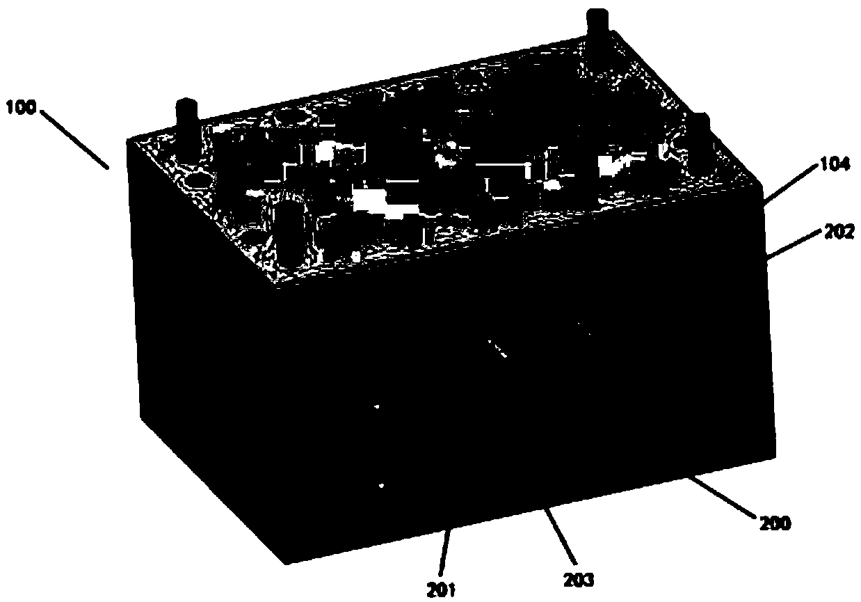
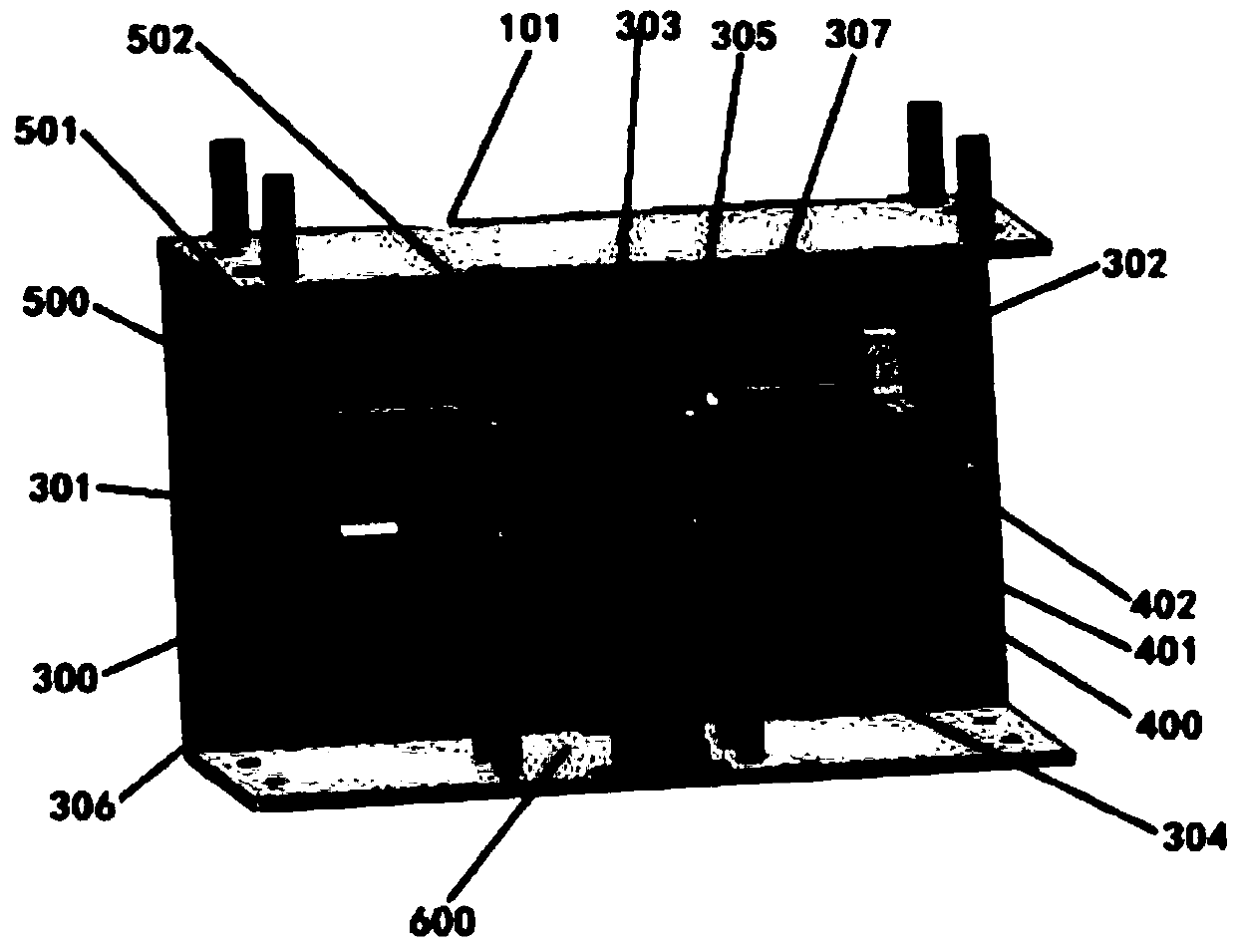
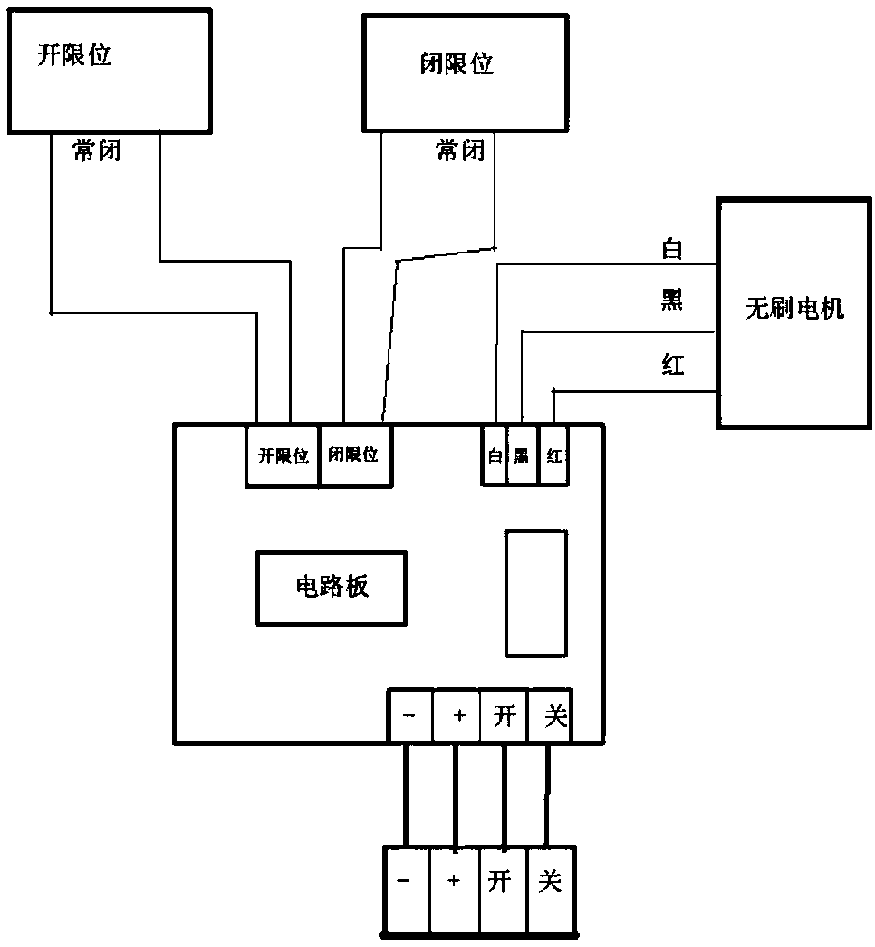
The invention provides a synchronous wheel driven elevator damping rail clamping device. The synchronous wheel driven elevator damping rail clamping device comprises a rail clamping device shell, a clamping mechanism, a transmission mechanism, a driving mechanism, a limiting switch and a control circuit board; the rail clamping device shell comprises a groove-shaped folded plate and three side plates which are used for closing the groove-shaped folded plate; two symmetrical rectangular through hole slideways are formed at the middle position of a front side plate of the groove-shaped folded plate; the clamping mechanism comprises two clamping guide blocks; the two clamping guide blocks are arranged on the outer sides of the two rectangular through hole slideways; the bottoms of the two clamping guide blocks are connected with the transmission mechanism arranged on the back sides of the rectangular through slideways; the transmission mechanism can drive the two clamping guide blocks tomove horizontally in the two rectangular through hole slideways; the driving mechanism is fixedly arranged on the back side of the front side plate through a supporting base; the driving mechanism isin transmission connection with the transmission mechanism; the limiting switch is arranged above the transmission mechanism and is used for limiting the horizontal movement distance of the clamping guide blocks; the limiting switch and the driving mechanism are electrically connected with the control circuit board; and the synchronous wheel driven elevator damping rail clamping device has the advantages of light weight, compact design, safety and reliability.

Description

technical field [0001] The invention relates to the technical field of manufacturing elevator safety components, in particular to an elevator damping rail clamp driven by a synchronous wheel. Background technique [0002] The rail clamp is a braking device that prevents the elevator car from accidentally moving when the door is opened. It is installed on both sides of the elevator car. Under normal conditions, when the elevator is running normally, the device does not work; when the elevator car is in the door-opening and stopping state, due to some fault in the elevator, the elevator runs unexpectedly, causing danger to passengers or goods entering or leaving the elevator. , the device acts and clamps the guide rail, thereby stopping the running elevator car to ensure the safety of passengers and goods. [0003] The patent with the existing notification number CN201310498779.X discloses a combined elevator rail clamp. The combined elevator rail clamp includes two mounting ...

Claims


Application Information

Patent Timeline
Patent Type & Authority Applications(China)
IPC IPC(8): B66B5/18
CPCB66B5/18
Inventor 曹文胤曹洋曹中毛一根张跃明程平刘小荣
Owner NANTONG YAO TELEI ELEVATOR PROD CO LTD
Learn More