Large-size additive-subtractive-integrated FDM printing head

A printing head, adding and subtracting material technology, applied in the field of additive manufacturing, can solve the problems that affect the surface accuracy and surface finish of printed parts, poor bonding force between parts, a large amount of plastic dust, etc., to achieve a good processing environment and a consistent surface Good performance, low land occupation and low cost

Pending Publication Date: 2019-04-26
NAT INST CORP OF ADDITIVE MFG XIAN
View PDF4 Cites 3 Cited by
  • Summary
  • Abstract
  • Description
  • Claims
  • Application Information

AI Technical Summary

Problems solved by technology

For example, in 2017, Shandong University of Technology developed a set of integrated machine for adding and subtracting materials for PEEK 3D printing. This all-in-one machine uses FDM technology combined with small milling machine tools to realize the integrated processing of adding and subtracting materials for PEEK, and has achieved certain results. However, the method of milling has its own limitations, and the integrated processing method has the following defects: 1) The immediacy is poor. After the molten plastic is extruded, a certain cooling time is required to cool it to a certain hardness. Suitable for cutting processing; 2) Due to the poor interlayer bonding force during plastic fused deposition molding, the local shear force of the processing head is received during the cutting process, which will lead to worse interlayer bonding force; 3) Mechanical cutting Processing will affect the surface accuracy and surface finish of printed parts; 4) Mechanical cutting processing will generate a large amount of plastic dust, causing environmental pollution
In summary, there is no particularly mature device or method in the prior art to print workpieces that meet the target size requirements at one time, and the printed parts have the problem of poor interlayer bonding

Method used


Image

  • Large-size additive-subtractive-integrated FDM printing head
  • Large-size additive-subtractive-integrated FDM printing head
  • Large-size additive-subtractive-integrated FDM printing head

Examples


Embodiment Construction

[0033] The present invention will be described in further detail below in conjunction with the accompanying drawings.

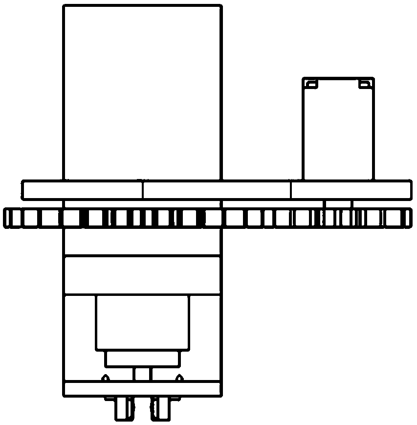
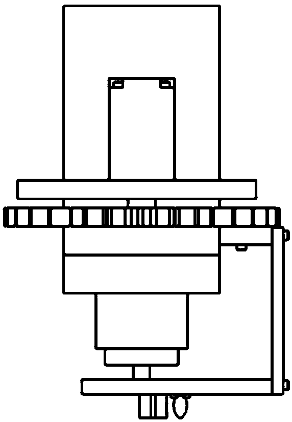
[0034] see figure 1 , figure 2 and image 3 , the present invention discloses an FDM print head integrating large-scale addition and subtraction materials, the print head includes a barrel 1, a motor 2, a motor mounting plate 3, a first fixing plate 4, a second fixing plate 5, a driving gear 6, Moving gear 7, print head 8, wedge-shaped heat channel 9, heat roller 10, rotating shaft 11, ball 12, flange 13, printing end 14, third fixing plate 15, cutting device 16, printing centerline 17, fixing Pile 18, cutter head 19.

[0035] see image 3 and Figure 4 , the upper surface of the motor mounting plate 3 is fixedly provided with a material cylinder 1 and the motor 2, and the material cylinder 1 and the motor 2 are not in contact; the lower surface of the motor mounting plate 3 is fixedly provided with a rotating shaft 11, the axis of the rotating shaft 11...


PUM


Abstract

The invention discloses a large-size additive-subtractive-integrated FDM printing head. According to the printing head, by arranging a cutting device and a hot roller device on the rear portion of theprinting head, if the defect that the two sides of a printed workpiece exceed the size of a model exists, the excessive parts are cut by the cutting device following behind; hot rollers are arrangedbehind the cutting device, a step is bridged through the hot rollers, thus, the concave part of the step is remedied by the protrusion part of the step, and the surface quality is improved; the layer-to-layer binding force is determined by the binding area of the concave part, thus, the layer-to-layer binding area is increased through the method, the layer-to-layer binding force is improved, and the mechanical property of the whole printed workpiece is improved; in the whole cutting process, organic dust is not generated, the machining environment is good, compared with existing mechanical subtractive manufacturing, the surface gloss after heat working and the surface consistency after 3D printing forming are good, and no obvious machining trace exits. A subtractive device is small in size, other machining equipment does not need to be arranged additionally, the occupied area is small, and the cost is low.

Description

【Technical field】 [0001] The invention belongs to the field of additive manufacturing, and in particular relates to an FDM print head integrating large-scale addition and subtraction of materials. 【Background technique】 [0002] In order to improve the printing efficiency, the fused deposition modeling (FDM) process needs to expand the diameter of the print head, but it increases the step effect of the product, making it more difficult to treat the surface quality of the workpiece, and it is difficult to improve the surface quality by means of grinding or polishing. [0003] Large-scale additive manufacturing parts can not only be used in aerospace and automotive fields, but also in home decoration, cultural and creative fields, etc., and have broad application prospects. For occasions with high requirements for industrial applications, the method of increasing first and then decreasing ensures the surface quality, but greatly increases the cost of equipment and reduces prod...

Claims


Application Information

Patent Timeline
Patent Type & Authority Applications(China)
IPC IPC(8): B29C64/209B29C64/20B33Y30/00
CPCB29C64/20B29C64/209B33Y30/00
Inventor 吴华英李昭勋成勇
Owner NAT INST CORP OF ADDITIVE MFG XIAN
Why Eureka
Try Eureka