Repair boring machine for hydraulic support cover beam

A technology of hydraulic supports and shielding beams, which is applied in the direction of boring/drilling, drilling/drilling equipment, metal processing equipment, etc., and can solve the problems of long boring cycle, equipment, types of work, multiple processes, and many processes. Achieve the effect of saving manpower and material resources and improving the efficiency of repair work

Active Publication Date: 2020-06-05
扎赉诺尔煤业有限责任公司
View PDF8 Cites 0 Cited by
  • Summary
  • Abstract
  • Description
  • Claims
  • Application Information

AI Technical Summary

Problems solved by technology

[0002] At present, after the hydraulic support is worn out in the long-term operation of the fully mechanized mining face, it is necessary to lift the worn hydraulic support to the mechanical repair shop on the ground, disassemble the hydraulic support, and then install the independent cover beam on a large boring machine for boring processing. The problem of the damaged hole is that in order to bore the damaged hole, it is necessary to lift the hydraulic support weighing about 30 tons from the 100-meter underground to the ground. The hydraulic support is disassembled, processed and assembled in the factory, and then The work can only be resumed after the hydraulic support is installed on the working face, which involves a lot of equipment, types of work and processes, and the boring cycle is long
[0003] Therefore, in order to solve the problems of boring and processing the repair of the damaged hole of the cover beam, which involves many equipment, types of work, processes and long boring cycle, a method for cutting and processing the damaged hole of the cover beam in the fully mechanized mining face of the coal mine is designed. It is necessary to repair the boring machine with the hydraulic support cover beam

Method used


Image

  • Repair boring machine for hydraulic support cover beam
  • Repair boring machine for hydraulic support cover beam
  • Repair boring machine for hydraulic support cover beam

Examples


Embodiment Construction

[0033] The specific embodiments of the present invention will be described in detail below in conjunction with the accompanying drawings, but it should be understood that the protection scope of the present invention is not limited by the specific embodiments.

[0034] Unless expressly stated otherwise, throughout the specification and claims, the term "comprise" or variations thereof such as "includes" or "includes" and the like will be understood to include the stated elements or constituents, and not Other elements or other components are not excluded.

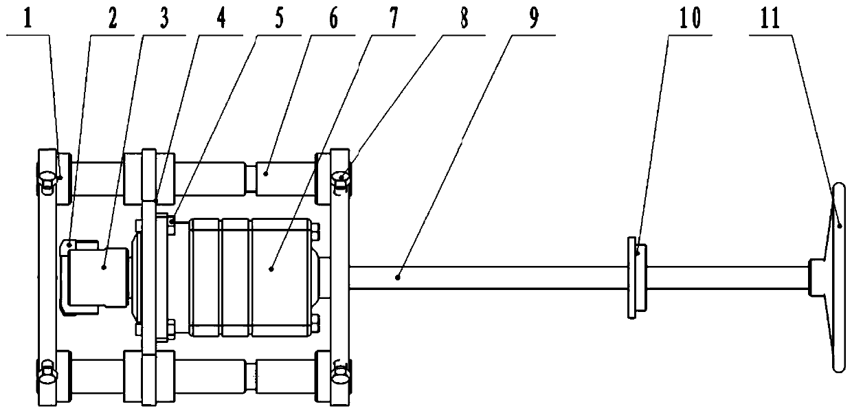
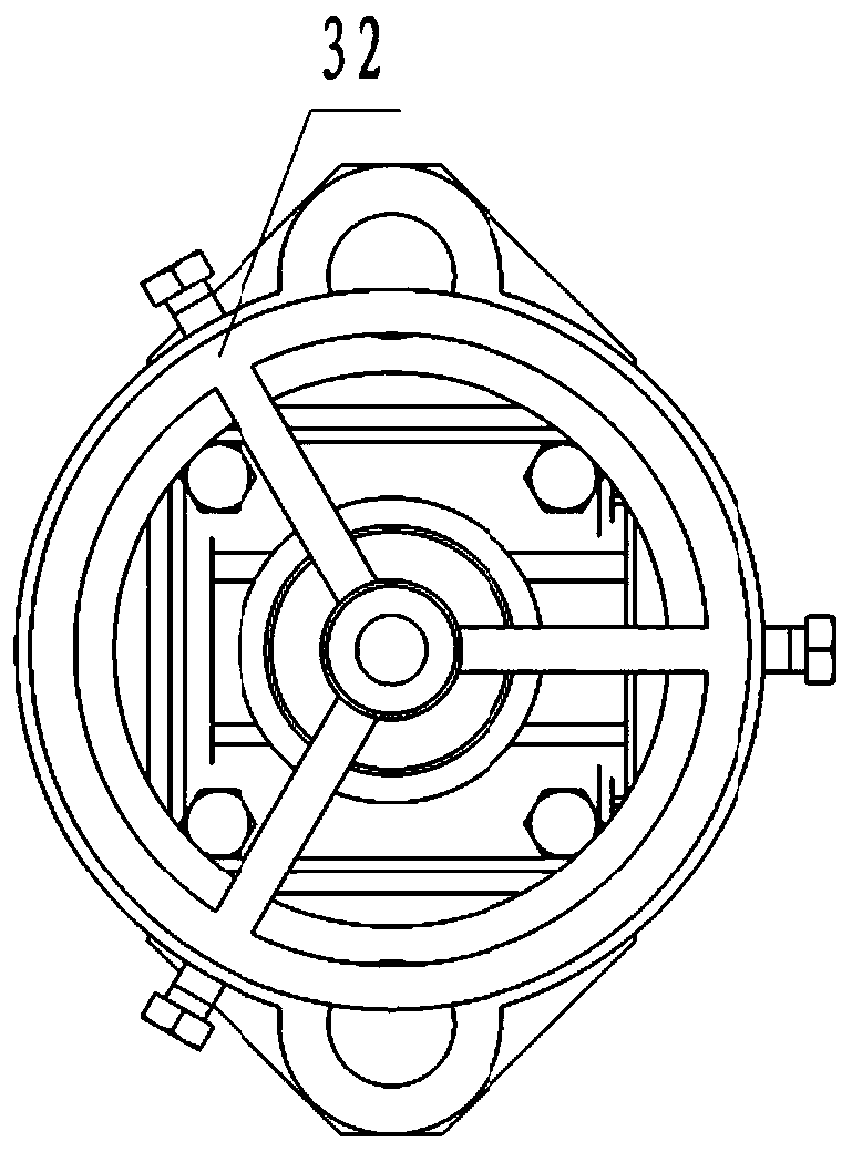
[0035] Such as Figure 1 to Figure 5 as shown, figure 1 It is a front view of a repair boring machine according to an embodiment of the present invention. figure 2 for figure 1 left view of . image 3 for figure 1 right view of . Figure 4 for figure 1 top view. Figure 5 It is a three-dimensional schematic view of a repair boring machine according to an embodiment of the present invention. A hydraulic support shi...


PUM


Abstract

The invention discloses a restoration hole boring machine of a hydraulic support beam cover. The restoration hole boring machine of the hydraulic support beam cover comprises a fastening device comprising two positioning plates and two guiding rods; each positioning plate is provided with two symmetrically formed positioning holes; and the two guiding rods are arranged between the two positioningplates in parallel, and the two ends of each guiding rod are arranged in the corresponding positioning holes in a penetrating manner correspondingly. A cutting device comprises a guiding disk, a hydraulic motor, a right-angle-U-shaped boring cutter and a cutter base; the two ends of the guiding disk are provided with guiding sleeves; the two guiding rods are sleeved with movable holes of the guiding sleeves, and movement along the guiding rods can be achieved; the guiding disk further comprises an alignment installing hole which is located in the center of the guiding disk; the hydraulic motoris installed in the alignment installing hole, and can move along with the guiding disk; and the right-angle-U-shaped boring cutter and the cutter base are arranged at the front end of the hydraulicmotor, and are driven by the hydraulic motor to rotate. A feeding device is in contact with the rear portion of the cutting device and the cutting device can be pushed to move forwards along the guiding rods. Thus, the restoration work can be completed underground, and both labor and time are saved.

Description

technical field [0001] The invention relates to the field of maintenance of coal mine mechanical equipment, in particular to a repair boring machine for a hydraulic support shield beam. Background technique [0002] At present, after the hydraulic support is worn out in the long-term operation of the fully mechanized mining face, it is necessary to lift the worn hydraulic support to the mechanical repair shop on the ground, disassemble the hydraulic support, and then install the independent cover beam on a large boring machine for boring processing. The problem of the damaged hole is that in order to bore the damaged hole, it is necessary to lift the hydraulic support weighing about 30 tons from the 100-meter underground to the ground. The hydraulic support is disassembled, processed and assembled in the factory, and then The work can only be resumed after the hydraulic support is installed on the working face, which involves a lot of equipment, types of work and processes, ...

Claims


Application Information

Patent Timeline
Patent Type & Authority Patents(China)
IPC IPC(8): B23B41/00
CPCB23B41/003
Inventor 李树森
Owner 扎赉诺尔煤业有限责任公司
Why Eureka
Try Eureka