Bottom mold locking device and using method thereof

A locking device and bottom mold technology, which is applied to other household appliances, applications, household appliances, etc., can solve the problems of lower bottom mold replacement efficiency, high assembly technology requirements, and bottom mold pull nails are easy to break, and improve replacement efficiency , Reduce the difficulty of operation, simplify the effect of operation

Active Publication Date: 2019-04-23
GUANGZHOU TECH LONG PACKAGING MACHINERY CO LTD
View PDF6 Cites 1 Cited by
  • Summary
  • Abstract
  • Description
  • Claims
  • Application Information

AI Technical Summary

Problems solved by technology

At present, the bottom mold pull stud connected with the bottom mold is usually used to cooperate with the bottom mold locking mechanism containing steel balls to realize the locking of the bottom mold. When the bottom mold is installed and disassembled, the bottom mold pull nail is locked with the bottom mold The coordination requirements of the mechanism are high, and the processing is difficult. The bottom mold is prone to jamming during installation, and the bottom mold pull nails are easy to break. Therefore, the assembly technology requirements for front-line workers are high, and the replacement efficiency of the bottom mold is reduced.

Method used


Image

  • Bottom mold locking device and using method thereof
  • Bottom mold locking device and using method thereof
  • Bottom mold locking device and using method thereof

Examples


Embodiment 1

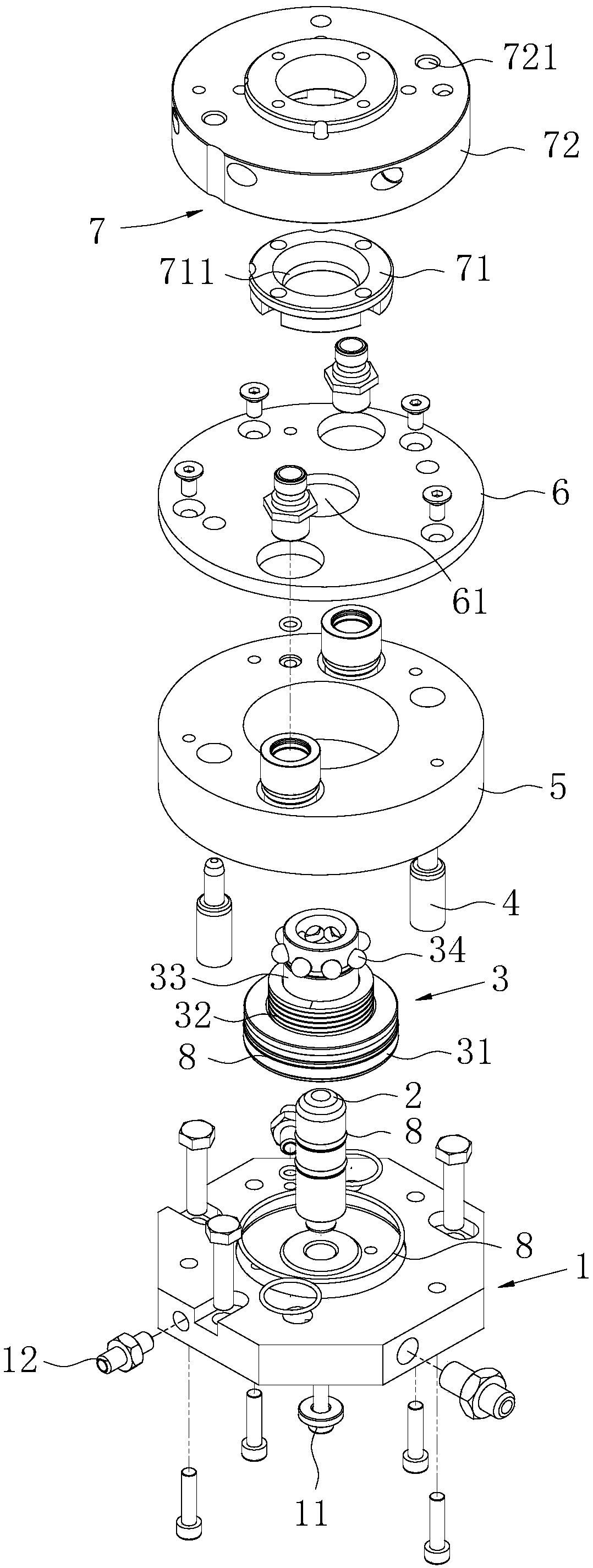
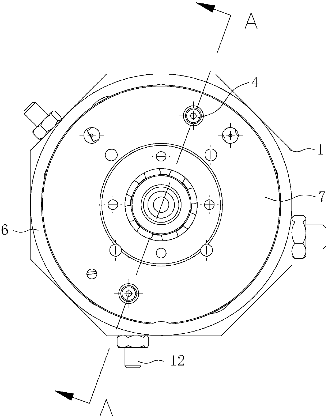
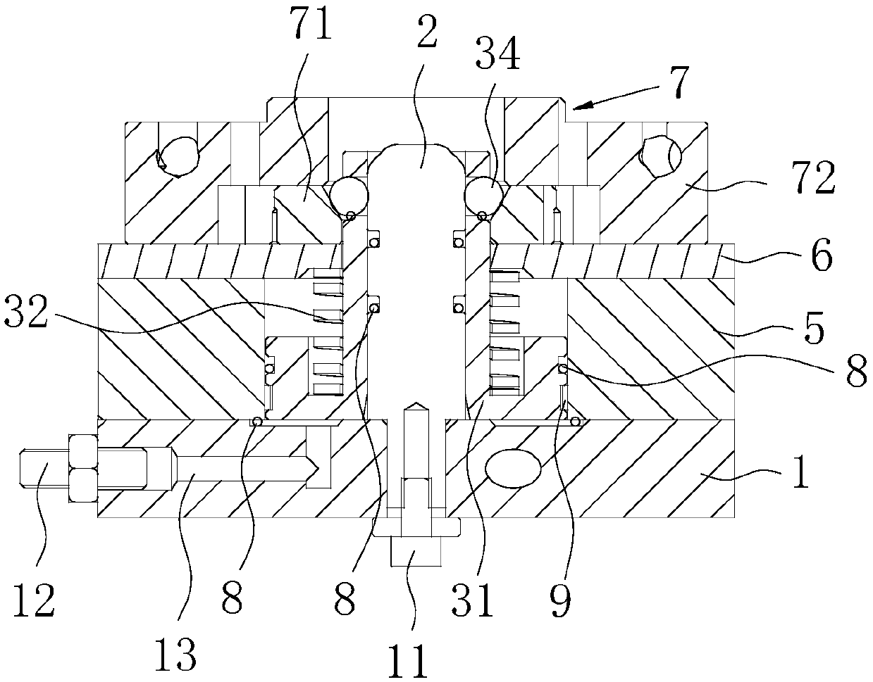
[0035] Such as Figure 1 to Figure 5 As shown, the bottom mold locking device of this embodiment includes a mounting base plate 1 , a positioning column 2 , a locking shaft 3 , a positioning pin shaft 4 , a hollow collar 5 , a cover plate 6 , a bottom mold connecting block 7 and a sealing ring 8 . The positioning column 2 is fixed on the installation base plate 1 by screws 11, the locking shaft 3 is sleeved on the positioning column 2 and can move along the axial direction of the positioning column 2, and the hollow collar 5 is sleeved on the outer periphery of the locking shaft 3 and connected to the installation base plate 1 Connected by screws, the cover plate 6 and the top of the hollow collar 5 are connected by screws, and the bottom mold connection block 7 is positioned on the top of the cover plate 6 through the positioning pin shaft 4 .

[0036] The locking shaft 3 includes a base 31 , a spring 32 , a body 33 and a locking ball 34 .

[0037] In this embodiment, the ba...

Embodiment 2

[0048] Such as image 3 As shown, on the basis of the first embodiment, a guide ring groove is provided on the base 31 of this embodiment, and a guide ring 9 is arranged inside the guide ring groove. By arranging the guide ring 9, on the one hand, the direct friction between the outer wall of the base 31 and the inner wall of the hollow collar 5 can be avoided, thereby prolonging the service life of the device; smooth.

Embodiment 3

[0050] Such as Figure 4 As shown, on the basis of any of the above-mentioned embodiments, the locking shaft 3 of this embodiment further includes a stop ring 35 disposed in the through hole of the body 33 on the side away from the positioning post 2 . The limiting ring 35 is located below the locking ball 34. When the locking ball 34 is in a movable state, the limiting ring 35 prevents the locking ball 34 from leaving the through hole of the body 33 in a direction away from the positioning column 2, preventing the locking ball 34 from falling from the side. fall.


PUM


Abstract

The invention discloses a bottom mold locking device and a using method thereof. The bottom mold locking device comprises a mounting bottom plate, a positioning column, a locking shaft, a hollow collar, a cover plate and a bottom mold connecting block, wherein the positioning column is fixed on the mounting bottom plate; the locking shaft is arranged on the side wall of the positioning column andmoves along the axial direction of the positioning column; the hollow collar is sleeved on the outer circumference of the locking shaft and connected with the mounting bottom plate; the cover plate isconnected to the top portion of the hollow collar; and the bottom mold connecting block is arranged at the top portion of the cover plate. According to the bottom mold locking device, the automatic alignment, centering, synchronous locking and the unlocking of the bottom mold locking process are achieved, the jam phenomenon is eliminated, the difficulty of replacing the bottom mold is greatly reduced, and the replacement efficiency of the bottom mold is improved.

Description

technical field [0001] The invention relates to the technical field of molds, in particular to a bottom mold locking device and a method for using the same. Background technique [0002] The blow molding machine is widely used in beverage bottles, medicine bottles, oil bottles and other fields. The blow molding station is the main part of the blow molding machine. The blow molding station is mainly composed of left, right and bottom molds. The combination of the three forms a complete bottle cavity. When the left and right molds are opened and the bottom mold is lowered, the bottle cavity is opened, the preform enters the bottle cavity, then the left and right molds are closed and the bottom mold rises to close the bottle cavity. At this time, the preform is blown. After molding, open the left and right molds and lower the bottom mold to open the bottle cavity, and take the molded bottle away, and so on. [0003] When the bottom mold is falling, it generally needs to be lo...

Claims


Application Information

Patent Timeline
Patent Type & Authority Applications(China)
IPC IPC(8): B29C49/00B29C49/48B29C49/56B29L22/00
CPCB29C49/0031B29C49/48B29C49/56B29C2049/566B29C2049/4856B29L2022/00
Inventor 吴志刚王燕囡肖兴强邓文杰
Owner GUANGZHOU TECH LONG PACKAGING MACHINERY CO LTD
Why Eureka
Try Eureka