Inverted defoaming device for conductive adhesive and application method thereof

A conductive adhesive and defoaming technology, applied in separation methods, chemical instruments and methods, circuits, etc., can solve the problems of unable to discharge a large amount of air from the piston and conductive adhesive, continuous and stable supply of conductive adhesive, and deterioration of dispensing, etc.

Inactive Publication Date: 2019-04-23
NO 24 RES INST OF CETC
View PDF6 Cites 1 Cited by
  • Summary
  • Abstract
  • Description
  • Claims
  • Application Information

AI Technical Summary

Problems solved by technology

Schematic diagram of centrifugal spin defoaming in conventional way figure 1 As shown, the special dispensing needle commonly used in the industry, the piston is a sheet-shaped bowl-shaped piston, which has poor airtightness, or the piston is separated from the needle tube, or even has no piston.
When centrifuging and degassing according to the conventional method with the tip down, if there is a piston, the air bubbles will not be easily discharged. If there is no piston, even if the conductive adhesive is fully degassed later, it cannot be discharged when the piston is installed. If there is a large amount of air, if the piston is not installed, the conductive adhesive will not be able to supply continuously and stably, which will worsen the dispensing

Method used


Image

  • Inverted defoaming device for conductive adhesive and application method thereof
  • Inverted defoaming device for conductive adhesive and application method thereof
  • Inverted defoaming device for conductive adhesive and application method thereof

Examples


Embodiment 1

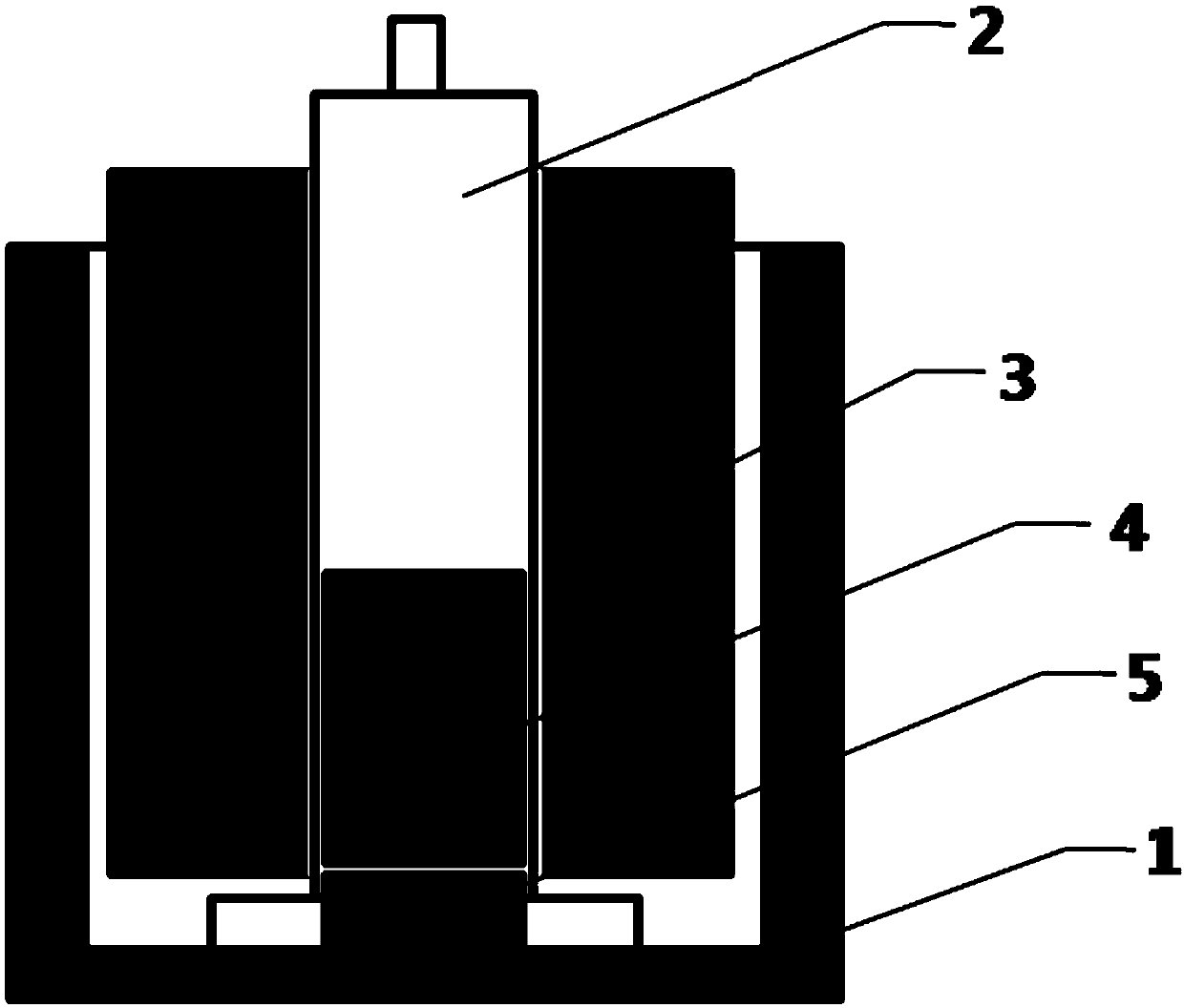
[0024] This embodiment provides a kind of conductive glue pouring defoaming device, such as figure 2 , the conductive adhesive inverted defoaming device includes a centrifuge, the centrifuge is provided with a base 1, a needle tube fixing fixture 3 and a needle tube 2, the outer shape of the base 1 is adapted to the centrifuge, and the inside of the base 1 is drawn out empty, and the inner surface is a thread structure; the needle tube fixing fixture 3 is a circular cylinder, and the outer surface of the needle tube fixing fixture 3 is a thread structure and matches the thread structure of the inner surface of the base 1; the outer surface of the typical needle tube fixing fixture of the present invention The size of the diameter is 0.2 mm smaller than the inner diameter of the base 1, and the inner diameter of a typical needle tube fixing fixture is 0.2 mm larger than that of the needle tube 2. Under this size, the devices are more closely matched.

[0025] Further, the need...

Embodiment 2

[0028] This embodiment provides a method for using a conductive adhesive inverted defoaming device, including the conductive adhesive inverted defoaming device provided in Example 1, specifically including the following steps:

[0029] S1. Install the conductive adhesive fixing device 3 on the base of the centrifuge;

[0030] S2. Pack the conductive adhesive in the barrel into the needle tube 2 after returning to temperature;

[0031] S3. Stand the needle tube 2 upside down, pull the piston of the needle tube 2 back to the bottom, break the piston push rod, and insert the needle tube upside down into the needle tube fixing fixture 3;

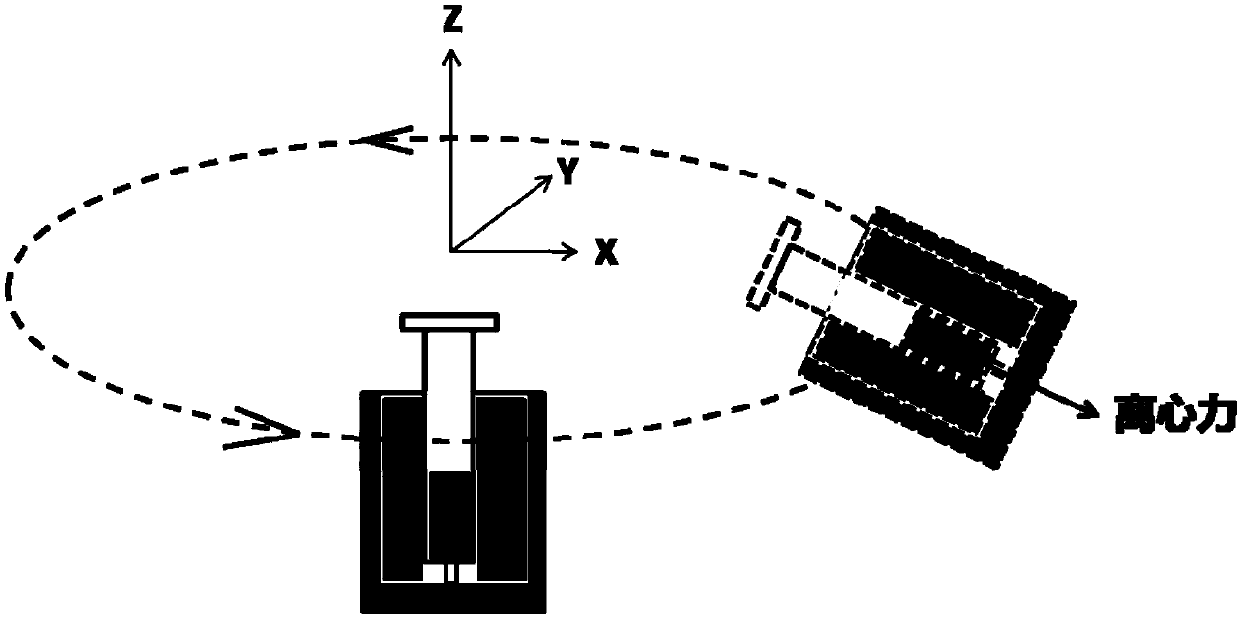
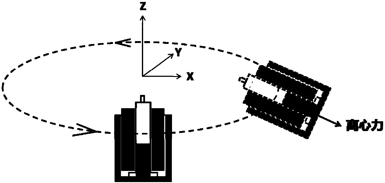
[0032] S4, together with the needle tube fixing fixture 3 and the needle tube 2, put them all into the base 1 of the centrifugal rotating device for centrifugal degassing, at this time, the centrifugal force on the conductive adhesive is outward, so that the air bubbles in the conductive adhesive are separated from the tip of the needle tube;

...


PUM


Abstract

The invention relates to the technical field of surface mounting processes in integrated circuit processes, in particular to an inverted defoaming device for conductive adhesive and an application method thereof. The inverted defoaming device for conductive adhesive comprises a centrifuge; a base, a needle tube fixture and a conductive adhesive fixing device are arranged on the centrifuge; the base matches with the centrifuge in shape; the base is hollowed inside and has an inner surface that is of threaded structure; the needle tube fixture is a ring column; the outer surface of the needle tube fixture is of threaded structure and matches with the threaded structure of the inner surface of the base; the conductive adhesive fixing device includes a piston and a needle tube; the needle tubeis of cylindrical hollow structure; the top of the needle tube is of pinhole structure; the bottom of the needle tube is extended out to form an outer ring; the outer radius of the outer ring is greater than the inner diameter of the needle tube fixture. The inverted defoaming device for conductive adhesive has the advantages that foam in conductive adhesive can be effectively removed, adhesive discharging for adhesive dispensing is more stable, the problems of unstable adhesive discharging, dispensing interruption, dispensed adhesive scattering and the like due to the inner foam in the conductive adhesive are solved, and the operating method is simple and convenient.

Description

technical field [0001] The invention relates to the technical field of patch technology in the integrated circuit technology, in particular to an inverted defoaming device for conductive adhesive and a use method thereof. Background technique [0002] The placement process in the integrated circuit packaging process is to fix the chip on the base of the case by bonding the epoxy resin conductive adhesive, which is an extremely important and indispensable process in the packaging process. The conductive adhesive used in the patch process is a special adhesive with both adhesion and conductivity before curing. In the SMT process, the chip is fixed on the bottom surface of the package by dispensing glue first and then patching, and then the conductive adhesive is hardened by heating and curing to form a stable bond between the chip and the bottom surface of the package. Among them, the amount of glue produced by the dispensing system and its stability will directly affect the ...

Claims


Application Information

Patent Timeline
IPC IPC(8): B01D19/02H01L21/56
CPCB01D19/0026B01D19/02H01L21/561
Inventor 李金龙
Owner NO 24 RES INST OF CETC
Why Eureka
Try Eureka