Optical fiber cutter capable of instantly storing cut optical fibers

A technology of optical fiber cutter and optical fiber, which is applied in the coupling direction of optical waveguide, can solve the problems of inability to realize the arc swing of the pendulum rod, complex structural design, and increased operation steps, so as to ensure the smoothness of automatic knife return and reduce the cutting process Effect of steps, stable opening and closing

Pending Publication Date: 2019-04-19
北京维新华通科技有限公司
View PDF3 Cites 0 Cited by
  • Summary
  • Abstract
  • Description
  • Claims
  • Application Information

AI Technical Summary

Problems solved by technology

[0011] 1. The horizontal pendulum is connected to the cutting assembly. As the cutting assembly is pushed forward, it can drive the rotating shaft of the horizontal pendulum to rotate, and then drive the mounting block to rotate. Through the first permanent magnet and the second permanent magnet With the projected coverage area of ​​the third permanent magnet and the fourth permanent magnet, when the cutting assembly cuts the optical fiber, the extension end of the swing arm is dropped, and then the cut optical fiber is clamped to prevent it from falling. The structural design is relatively complicated, relying on the coverage area between the magnets to control the whereabouts of the extension of the swing arm, the reliability is poor;
[0012] 2. The above-mentioned invention has relatively large design defects. The lower end of the rotating shaft is vertically connected to the right end of the horizontal swing rod, and the left end of the swing rod away from the rotating shaft is connected to the lower rear side of the cutter head, while the cutting assembly slides longitudinally on the guide rail, and the rotating shaft The rotation of the pendulum needs to rely on the pendulum to swing in the waist circular hole, which requires the pendulum to rotate around the rotation axis of the shaft, but the arc swing of the pendulum cannot be realized in the instructions and drawings. It should be noted that, The sliding distance of the cutting assembly is not short. If the impossibility of the swing rod is excluded, the swing rod has a large movable space at the rear connection of the swing rod and the cutter head, which is enough to support the arc rotation of the swing rod. Flexible, and the swing of the pendulum is also imprecise;
[0013] 3. Since the existing light cutter has the function of automatic recovery of the cutting component after cutting (automatic knife return), and the comparison document uses a swing rod to connect the cutting component, which affects the automatic recovery of the cutting component;
[0014] 4. In order to ensure that the cutting device will not move backwards after a forward cut and cause damage to the optical fiber, the limit assembly must be able to limit the cutting assembly, so when it is necessary to send the broken optical fiber into the storage box, and carry out When preparing to cut the optical fiber next time, the invention can only open the large and small pressure plates first, and then move the cutting assembly backwards to open the extension section of the swing arm, which has poor structural relevance and increased operating steps. have good flexibility

Method used


Image

  • Optical fiber cutter capable of instantly storing cut optical fibers
  • Optical fiber cutter capable of instantly storing cut optical fibers
  • Optical fiber cutter capable of instantly storing cut optical fibers

Examples


Embodiment Construction

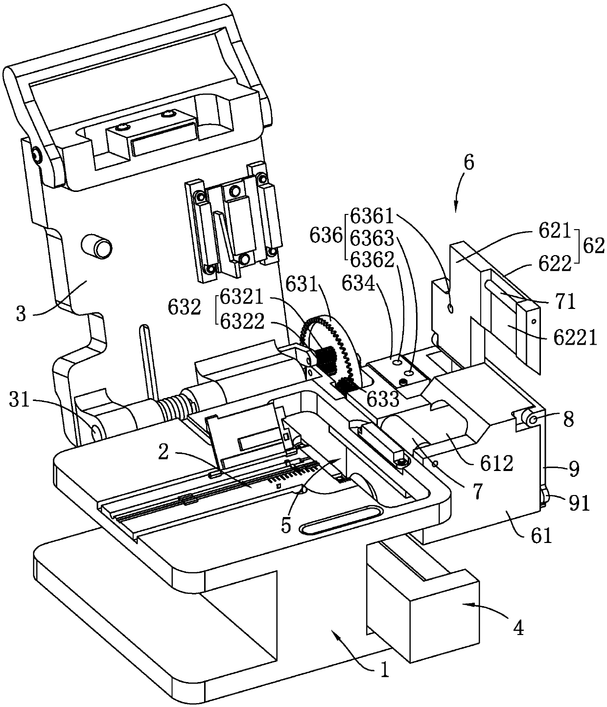
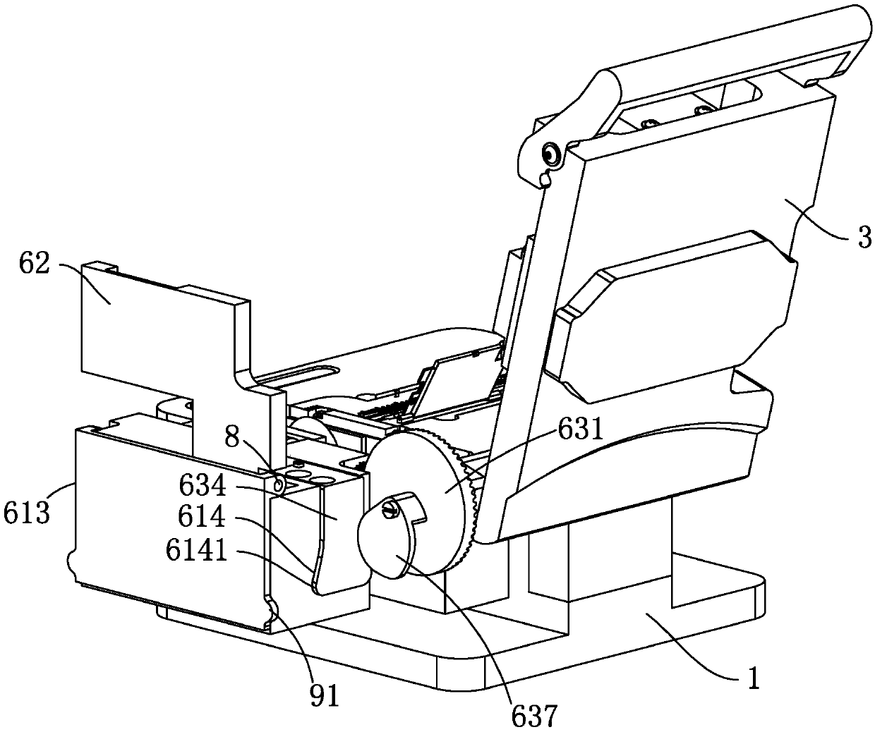
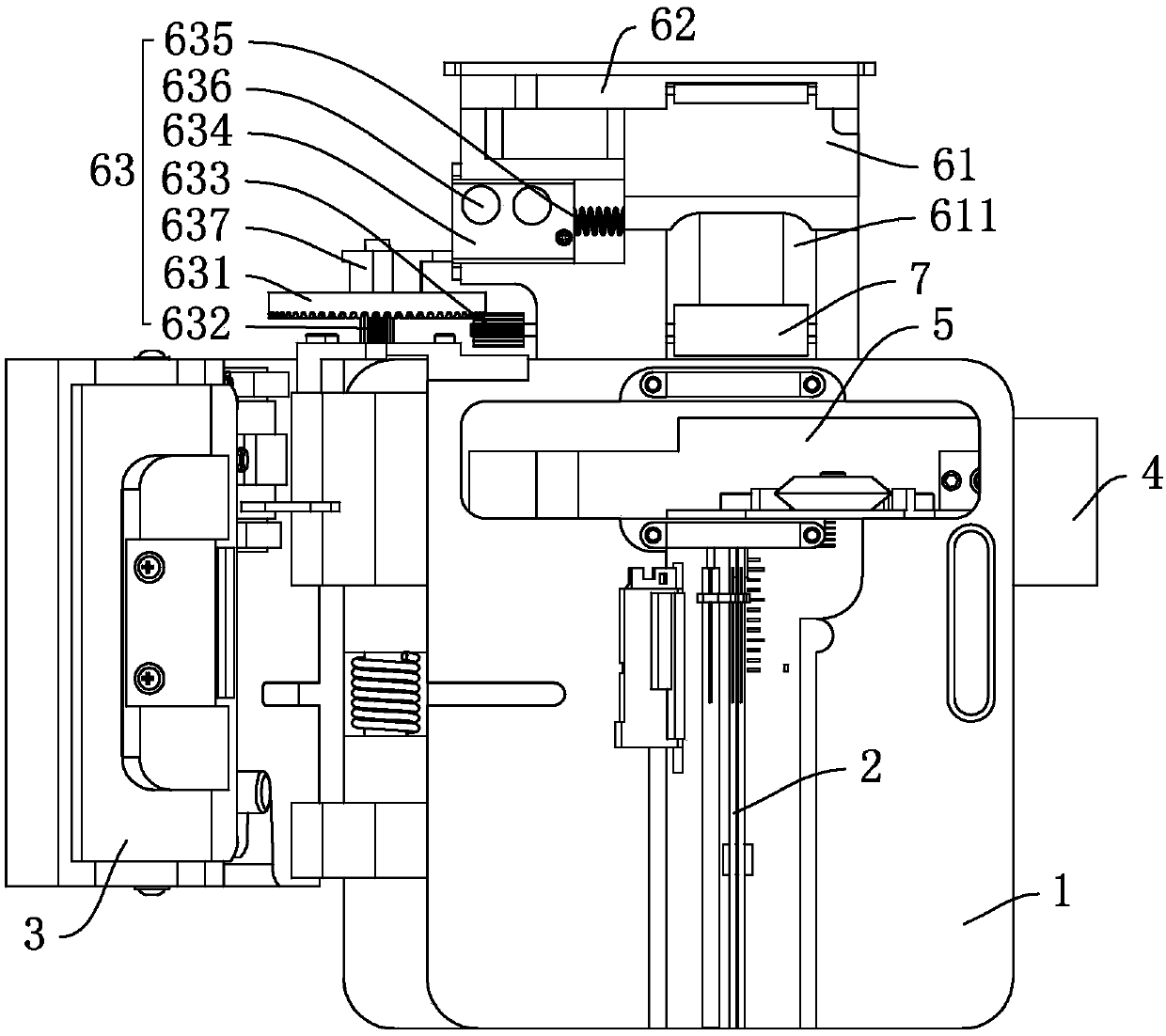
[0064] Reference figure 1 , Which is an optical fiber cleaver capable of instantaneously accommodating broken optical fibers after cleavage according to the present invention, including a main body 1, a gland 3 and a sliding cutting assembly 4. Among them, the main body 1 has an optical fiber guide portion 2 arranged on the upper surface, and its main function is to position the optical fiber; the gland 3 is hinged on a horizontal gland shaft 31 arranged on the main body 1 and parallel to one side of the optical fiber guide portion 2. On one side of the main body 1, the pressing cover 3 is turned up and opened relative to the upper surface of the main body 1 with the horizontal pressing shaft 31 as an axis, and is turned down to cover the optical fiber guide portion 2; the sliding cutting assembly 4 is slidably connected to the main body 1, It is located below the notch 5 at the end of the fiber guiding end, and can be configured to cut the optical fiber through the notch 5 in t...


PUM


Abstract

The invention relates to an optical fiber cutter capable of instantly storing cut broken optical fibers. The optical fiber cutter comprises a main body having an optical fiber guide portion, a gland which is hinged to one side of the main body through a horizontal gland shaft, a sliding cutting assembly, and an external storage box which is used for receiving the cut broken optical fibers. The storage box is provided with a box body, a swing arm and a linkage assembly, the box body is provided with a receiving opening and a discharging opening, and the front end of the receiving opening is provided with a driving guide roller; the swing arm is hinged to the storage box through a horizontal swing arm shaft; the linkage assembly is respectively connected with the gland, the driving guide roller and the swing arm, and synchronously links the rotation of the driving guide roller and the overturning of the swing arm along with the overturning of the gland; and when the gland is turned downwards to cover the main body, the driving guide roller rotates in the direction which is reverse to the direction in which the optical fiber guide portion guides the optical fibers to enter the cutter.The optical fiber cutting device has the advantages that the broken optical fibers formed after the optical fibers are cut can be timely and effectively stored, the relevance of the designed structure is strong, and the optical fiber cutting operation is facilitated.

Description

Technical field [0001] The present invention relates to the technical field of optical fiber cutting, and in particular to an optical fiber cleaver capable of instantaneously storing the broken optical fibers after cutting. Background technique [0002] The fiber cleaver is a tool for cutting the optical fiber during the fiber fusion process. [0003] The existing Chinese invention patent with the authorized announcement number CN102971651B discloses an optical fiber cleaver. With reference to its specific implementation and the accompanying drawings, the optical fiber cleaver includes: a main body and a cover, which can be opened using a shaft The main body is connected to the main body together; the main body includes: a base, a mounting table, the mounting table is arranged above the base; and a connecting part that connects the base and the mounting table with each other. The mounting table has an optical fiber guide part for positioning the optical fiber; the sliding member i...

Claims


Application Information

Patent Timeline
IPC IPC(8): G02B6/25
CPCG02B6/25Y02W30/66
Inventor 师振江徐希君葛薇
Owner 北京维新华通科技有限公司
Why Eureka
Try Eureka