
Constant-temperature heat pump unit for greenhouse and control method thereof

A pump unit and warming technology, applied in the field of constant temperature in greenhouses, can solve problems such as reduced efficiency, difficult maintenance, and scaling of pipes, achieving good heat exchange effects and ensuring normal operation

Pending Publication Date: 2019-04-19
GUANGDONG PHNIX ECO ENERGY SOLUTION
View PDF6 Cites 1 Cited by
  • Summary
  • Abstract
  • Description
  • Claims
  • Application Information

AI Technical Summary

Problems solved by technology

[0003] 1. The roof truss combined pipe network is used for water circulation heat storage and constant temperature. This type of greenhouse is greatly affected by geography and environment, and the land utilization rate is low. It can only be used for heating and cannot be used for cooling. It has many disadvantages and is not suitable for large-scale planting;
[0004] 2. The ground source heat pump is used for constant temperature, and the utilization of underground water sources is more restricted. The energy saving efficiency of the ground source heat pump is high, but long-term use faces many problems such as pipeline fouling, reduced efficiency, and difficult maintenance;
[0005] 3. The combination of natural gas boiler + greenhouse heat pipe is used to keep the temperature. The temperature required for heat pipe transportation is not lower than 40 degrees, but the heat transfer efficiency is low, the density of pipeline laying is high, the investment cost is high, and it cannot meet the cooling demand in summer, and additional cooling sources are required.

Method used


Image

  • Constant-temperature heat pump unit for greenhouse and control method thereof

Examples


Embodiment Construction

[0027] The following will clearly and completely describe the technical solutions in the embodiments of the present invention with reference to the accompanying drawings in the embodiments of the present invention. Obviously, the described embodiments are only some, not all, embodiments of the present invention. Based on the embodiments of the present invention, all other embodiments obtained by persons of ordinary skill in the art without creative efforts fall within the protection scope of the present invention.

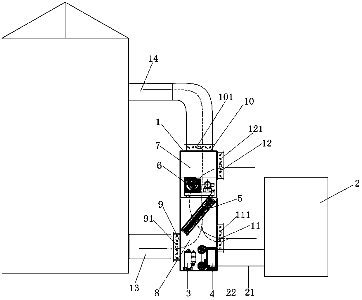
[0028] Such as figure 1As shown, a preferred embodiment of a greenhouse constant temperature heat pump unit provided by the present invention includes a body 1 and a water tank 2, and a compressor 3, a first heat exchanger 4, and a second heat exchanger 5 are arranged inside the body 1 and the fan module 6, the fan module 6 divides the inner cavity of the body 1 into upper and lower parts of the air outlet chamber 7 and the air inlet chamber 8, the negative pressur...


PUM


Abstract

The invention discloses a constant-temperature heat pump unit for a greenhouse. The constant-temperature heat pump unit for the greenhouse comprises machine body and a water tank, wherein a compressor, a first heat exchanger, a second heat exchanger and a fan module are arranged inside the machine body; the fan module divides the inner cavity of the machine body into an upper part and a lower partof an air outlet cavity and an air inlet cavity, the compressor, the first heat exchanger and the second heat exchanger are all fixedly installed in the air inlet cavity, the second heat exchanger isclose to a negative pressure side of the fan module, and an air inlet cavity is provided with a first air inlet communicating with air in the greenhouse; the first air inlet is located below the second heat exchanger, the air outlet cavity is provided with a first air outlet communicating with the air in the greenhouse, the water tank is arranged outside the machine body and is connected with thefirst heat exchanger; the invention further discloses a control method applying the greenhouse constant-temperature heat pump unit. According to the unit and the method, the requirements of refrigeration and heating in the greenhouse can be met; moreover, due to the arrangement of the water tank, the heat pump unit can generate a better heat exchange effect with the first heat exchanger during operation, and the normal operation of the heat pump unit is ensured.

Description

technical field [0001] The invention belongs to the technical field of greenhouse constant temperature, and more specifically relates to a greenhouse constant temperature heat pump unit and a control method thereof. Background technique [0002] At present, greenhouses are usually carried out in three ways: roof truss combined pipe network water circulation heat storage constant temperature, ground source heat pump constant temperature, natural gas boiler + greenhouse heat pipe combination constant temperature. Although these three methods can achieve constant temperature in greenhouses, there are the following problems: [0003] 1. The roof truss combined pipe network is used for water circulation heat storage and constant temperature. This type of greenhouse is greatly affected by geography and environment, and the land utilization rate is low. It can only be used for heating and cannot be used for cooling. It has many disadvantages and is not suitable for large-scale plant...

Claims


Application Information

Patent Timeline
Patent Type & Authority Applications(China)
IPC IPC(8): F24F3/00F24F7/08F24F11/72F24F11/89F24F13/00F24F13/30A01G9/24F24F110/70
CPCA01G9/245F24F3/001F24F7/08F24F11/72F24F11/89F24F13/00F24F13/30F24F2110/70Y02A40/25Y02P60/14
Inventor 雷朋飞吴东华刘远辉高翔刘辉吴思朗叶景发朱晓广廖立元刘志力梁华锋
Owner GUANGDONG PHNIX ECO ENERGY SOLUTION
Learn More