
Ship toilet negative-pressure screw pushing gas-liquid conveying device

A conveying device and gas-liquid technology, which is applied in the field of gas-liquid conveying devices and conveying devices, can solve the problems of strong odor and unclean cleaning, and achieve the effect of simple structure, good deodorizing effect and clean cleaning

Pending Publication Date: 2019-04-19
台州海百纳船舶设备股份有限公司
View PDF0 Cites 1 Cited by
  • Summary
  • Abstract
  • Description
  • Claims
  • Application Information

AI Technical Summary

Problems solved by technology

[0002] Ships are commonly used means of transportation on the sea and rivers. Because they are water vehicles, toilet sewage and deodorization are very difficult problems, especially for seagoing ships with long sailing distances. At present, ship toilets are often located at the bottom of the toilet or at the bottom of the toilet. A centrifugal pump is installed at the back to flush the feces and other dirt. Since no negative pressure can be generated, there are often serious problems such as unclean cleaning and strong odor. To solve such problems, it is necessary to design a ship toilet conveying device to solve the above problems

Method used


Image

  • Ship toilet negative-pressure screw pushing gas-liquid conveying device
  • Ship toilet negative-pressure screw pushing gas-liquid conveying device
  • Ship toilet negative-pressure screw pushing gas-liquid conveying device

Examples


Embodiment Construction

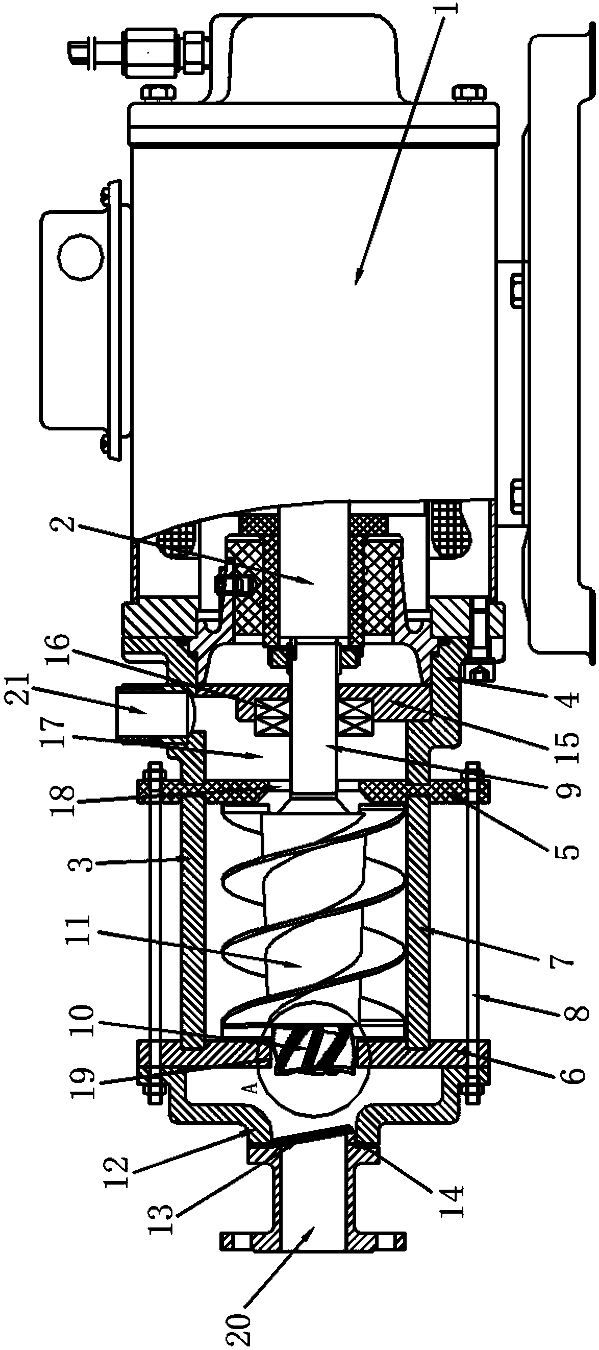
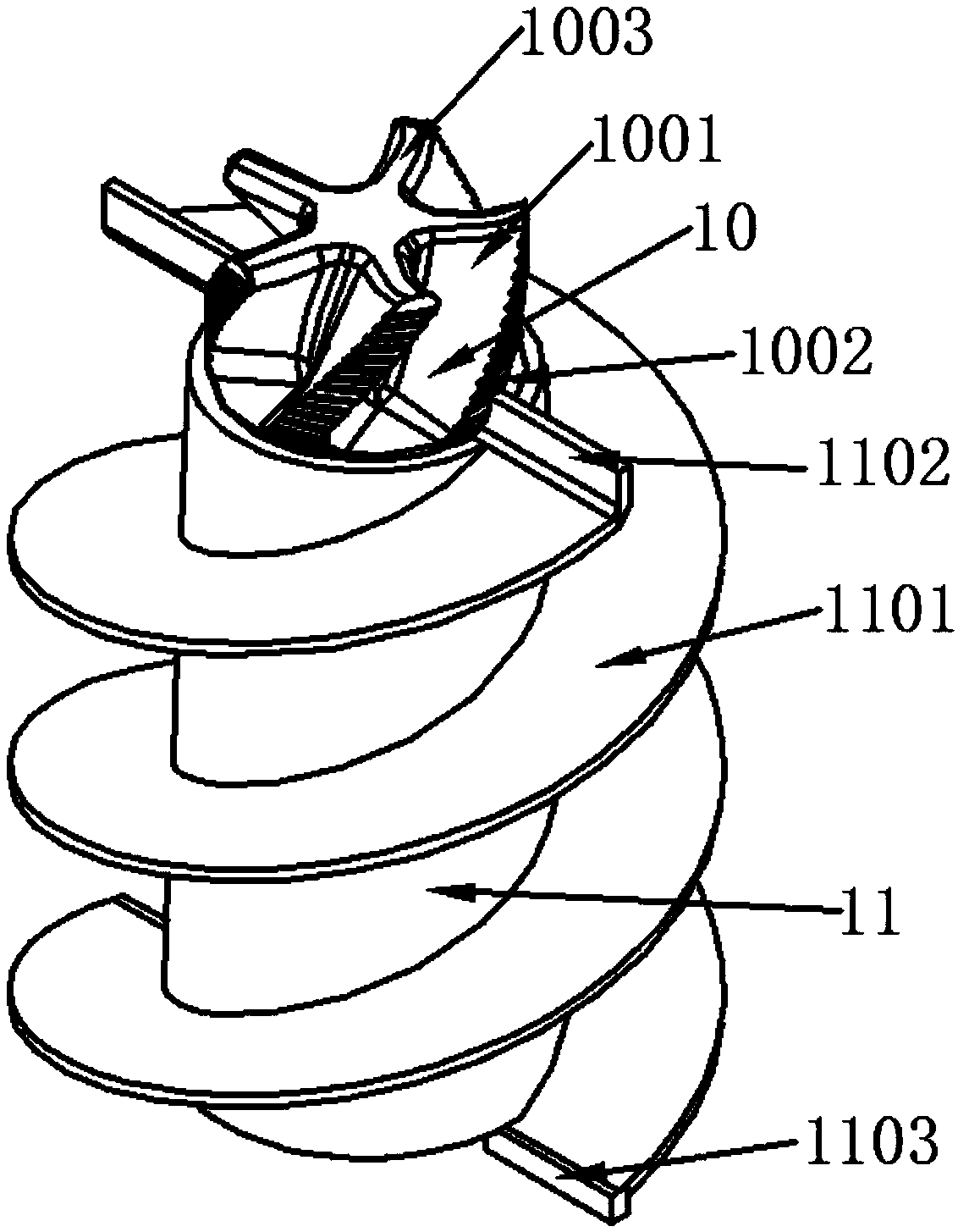
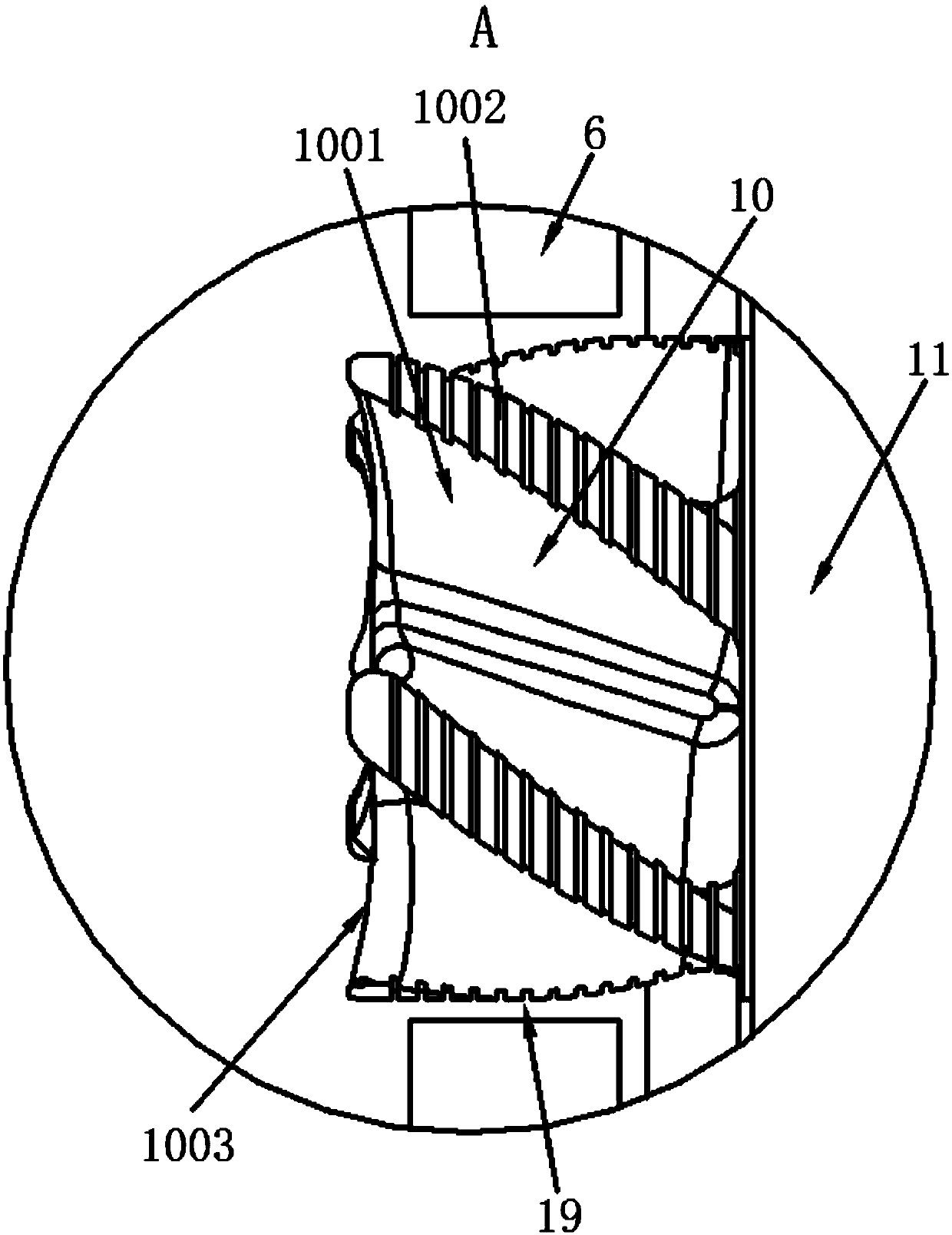
[0017] refer to Figure 1-Figure 3 , a negative pressure rotary gas-liquid conveying device for marine toilets of the present invention, comprising a motor 1, a gas-liquid conveying device 3, a conveying shaft 9, a non-return baffle 13, a sewage inlet 20 and a sewage discharge port 21, one end of the motor 1 A motor connector 4 is connected, and an air-liquid delivery device 3 is connected to one end of the motor connector 4. The gas-liquid delivery device 3 includes a first connecting plate 5, a second connecting plate 6, a ring column 7, and a delivery terminal 10 , screw sleeve 11 and inlet end cover 12, one end of the output shaft of the motor 1 is connected with a conveying shaft 9, and the conveying shaft 9 passes through the round hole and the sealing sleeve 16 on the partition plate 15 inside the motor connector 4, and the sealing sleeve 16 Set in the round hole; one end of the motor connector 4 is connected to the side of the first connecting plate 5, a ring column 7 ...


PUM

PropertyMeasurementUnit
Helix angleaaaaaaaaaa

Abstract

The invention discloses a ship toilet negative-pressure screw pushing gas-liquid conveying device which comprises a motor, a gas-liquid conveying device body, a conveying rotation shaft, a non-returnbaffle plate, a dirt inlet and a dirt outlet. One end of the motor is connected with a motor connector, one end of the motor connector is connected with the gas-liquid conveying device body, one end of an output shaft of the motor is connected with the conveying rotation shaft, one end of the motor connector is connected with the side face of a first connecting plate, a circular ring column is arranged between the first connecting plate and a second connecting plate, one end of the conveying rotation shaft is connected with a conveying tip, a spiral sleeve is arranged on the outer side wall ofthe conveying rotation shaft, the conveying rotation shaft penetrates a middle drain hole in the first connecting plate, the conveying tip penetrates a suction opening in the second connecting plate,an inlet end cover is arranged on one side of the second connecting plate, the non-return baffle plate is hinged into the inlet end cover, and a drain outlet is formed in the side wall of the motor connector and communicated with a liquid outlet cavity. The ship toilet negative-pressure screw pushing gas-liquid conveying device is simple in structure, ingenious in design, complete in cleaning andgood in deodorization effect and can be widely popularized and applied.

Description

【Technical field】 [0001] The invention relates to the technical field of delivery devices, in particular to the technical field of gas-liquid delivery devices. 【Background technique】 [0002] Ships are commonly used means of transportation on the sea and rivers. Because they are water vehicles, toilet sewage and deodorization are very difficult problems, especially for seagoing ships with long sailing distances. At present, ship toilets are often located at the bottom of the toilet or at the bottom of the toilet. A centrifugal pump is installed at the back to flush the feces and other dirt. Since no negative pressure can be generated, there are often serious problems such as unclean cleaning and strong odor. To solve such problems, it is necessary to design a ship toilet conveying device to Solve the above problems. 【Content of invention】 [0003] The purpose of the present invention is to solve the problems in the prior art, and propose a negative pressure rotary push ga...

Claims


Application Information

Patent Timeline
IPC IPC(8): E03F1/00B63B29/16B63B29/14
CPCE03F1/006B63B29/14B63B29/16
Inventor 连加俤
Owner 台州海百纳船舶设备股份有限公司
Learn More