
An e-waste recycling device that prevents sucked-out solder from reflowing through the bracket limit

A technology of electronic waste and recovery device, which is applied in the direction of transportation and packaging, solid waste removal, chemical instruments and methods, etc. It can solve the problem that solder is easy to stick to the inner wall of the equipment, which affects the recovery work, and it is difficult to find electrical filaments. And other issues

Inactive Publication Date: 2021-09-07
LANZHOU UNIVERSITY
View PDF9 Cites 0 Cited by
  • Summary
  • Abstract
  • Description
  • Claims
  • Application Information

AI Technical Summary

Problems solved by technology

[0002] The current solder recovery device usually uses negative pressure inching to melt the solder at high temperature, and then manually moves the fixed electrical appliance to join the filaments, sucking the solder out and placing it inside the same pipeline, but this method is likely to cause:
[0003] When performing recycling work, by placing the solder inside the same pipe, it is easy to condense the internal solder again during the secondary recovery work, and when it is adsorbed, the internal solder is easy to stick to the inner wall of the equipment, so that Solder spots are easily formed inside the recovery device, which will affect the next recovery work. At the same time, the filament needs to be moved manually. The smoke generated after the temperature-sensitive melting of the solder will affect the identification ability of the staff, making it difficult to remove the electrical filament. Find out the work that affects recycling

Method used


Image

  • An e-waste recycling device that prevents sucked-out solder from reflowing through the bracket limit
  • An e-waste recycling device that prevents sucked-out solder from reflowing through the bracket limit
  • An e-waste recycling device that prevents sucked-out solder from reflowing through the bracket limit

Examples


Embodiment

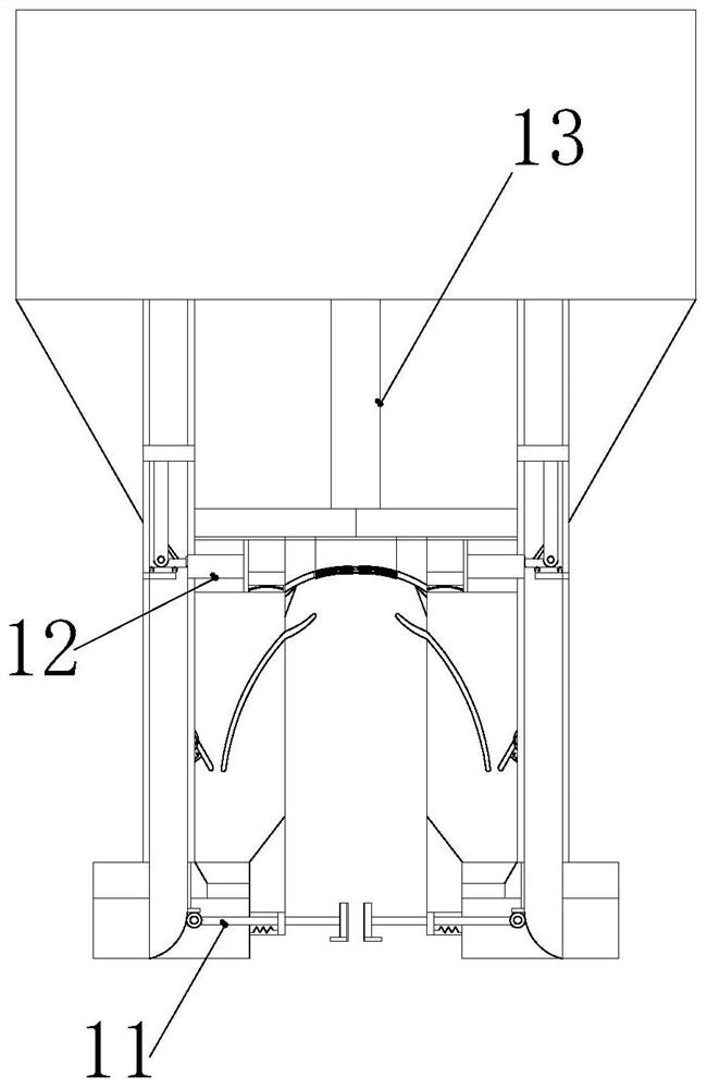
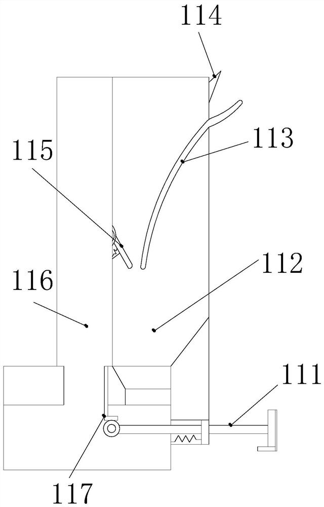
[0027] see figure 1, the present invention provides an electronic waste recovery device that prevents solder from being sucked out and reflowed through the limit of the bracket. The device 1 is located on the lower end surface of the device housing 4 and is movably connected with the device housing 4. The card slot 2 is located inside the device housing 4 and is movably connected with the device housing 4. The hose 5 is located in the device housing. The upper surface of the body 4 is connected to the device housing 4 at the same time, the adjustment block 3 is located on the outer surface of the card slot 2 and is in clearance fit with the card slot 2, and the hose 5 is connected to the external negative pressure fan through the Together, the direction can be adjusted conveniently through the hose 5 so as to be connected with the external negative pressure fan.

[0028] see figure 2 , the present invention provides an electronic waste recovery device that prevents sucked o...


PUM


Abstract

The invention discloses an electronic waste recovery device that prevents sucked-out solder from reflowing through the limit of a bracket. The side end surface is flexibly connected with the device housing at the same time, and the card slot is located inside the device housing and is movably connected with the device housing. After the solder is melted by high temperature, the upper rod is pressed down, so that the lower special-shaped rod continues to press down. Therefore, the rollers are used to move the special-shaped rod to make the front push rod frame move forward, and the internal filaments are fixed by the push rod frame through the inward joint of both ends without manual manipulation. At the same time, it is absorbed by the negative pressure tube and soldered at the same time. It is sucked out and clamped on the matching frame, and the solder is cooled under the cooling of the gas flow, and is recycled to the interior of the disconnected collection chamber through the scraper and the inclined plate, thereby preventing the secondary solidification of the solder.

Description

technical field [0001] The invention relates to the field of motor waste recycling, in particular to an electronic waste recycling device that prevents sucked-out solder from reflowing through the limit position of a bracket. Background technique [0002] The current solder recovery device usually uses negative pressure inching to melt the solder at high temperature, and then manually moves the fixed electrical appliance to join the filaments, sucking the solder out and placing it inside the same pipeline, but this method is likely to cause: [0003] When performing recycling work, by placing the solder inside the same pipe, it is easy to condense the internal solder again during the secondary recovery work, and when it is adsorbed, the internal solder is easy to stick to the inner wall of the equipment, so that Solder spots are easily formed inside the recovery device, which will affect the next recovery work. At the same time, the filament needs to be moved manually. The s...

Claims


Application Information

Patent Timeline
Patent Type & Authority Patents(China)
IPC IPC(8): B09B3/00B09B5/00
CPCB09B5/00B09B3/40
Inventor 李一翰谢鸿远
Owner LANZHOU UNIVERSITY
Learn More