
Eddy current compensation method and eddy current compensation system

A compensation method and compensation system technology are applied in the field of magnetic detection, which can solve the problems of complicated electromagnetic detection steps and low accuracy.

Active Publication Date: 2020-10-20
SHANGHAI INST OF MICROSYSTEM & INFORMATION TECH CHINESE ACAD OF SCI +1
View PDF5 Cites 0 Cited by
  • Summary
  • Abstract
  • Description
  • Claims
  • Application Information

AI Technical Summary

Problems solved by technology

[0006] In view of the shortcomings of the prior art described above, the purpose of the present invention is to provide an eddy current compensation method and an eddy current compensation system, which are used to solve the problems of cumbersome electromagnetic detection steps and low accuracy in the prior art

Method used


Image

  • Eddy current compensation method and eddy current compensation system
  • Eddy current compensation method and eddy current compensation system
  • Eddy current compensation method and eddy current compensation system

Examples


Embodiment 1

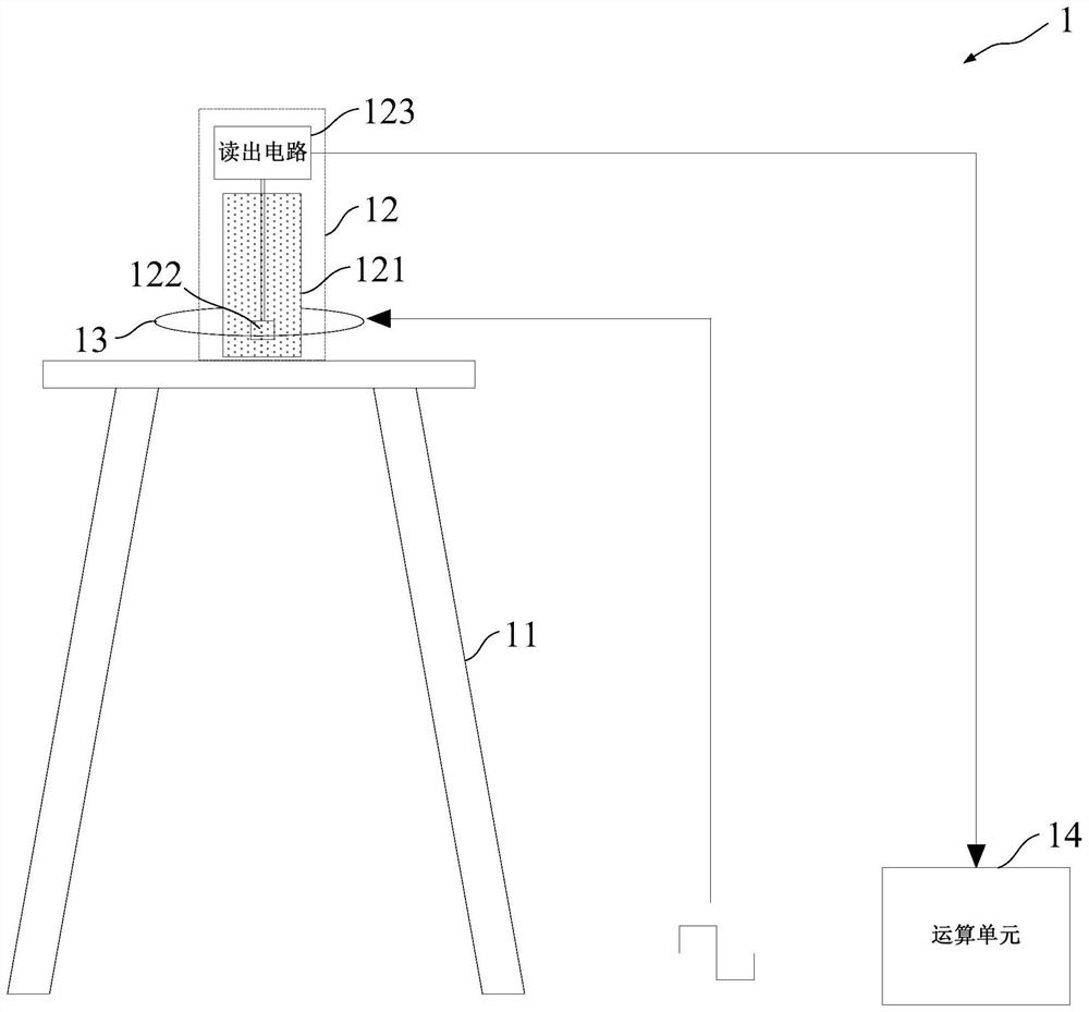
[0048] Such as figure 1 As shown, the present embodiment provides a system 1 for eddy current compensation, and the eddy current compensation system 1 includes:

[0049] An insulating support 11 , a SQUID system 12 , an excitation coil 13 and a computing unit 14 .

[0050] Such as figure 1 As shown, the insulating support 11 is used to place the SQUID system 12 .

[0051] Specifically, in this embodiment, the material of the insulating bracket 11 is wood. In actual use, any material that does not affect the response of the measured object and does not generate eddy currents is suitable for the present invention, and it will not be mentioned here. repeat. The height of the insulating support 11 is set to reduce or avoid the influence of the earth's magnetic field on the detection results. In this embodiment, the height of the insulating support is set to be not less than 10m, and the higher the height of the insulating support 11 , the earth's magnetic field has less influe...

Embodiment 2

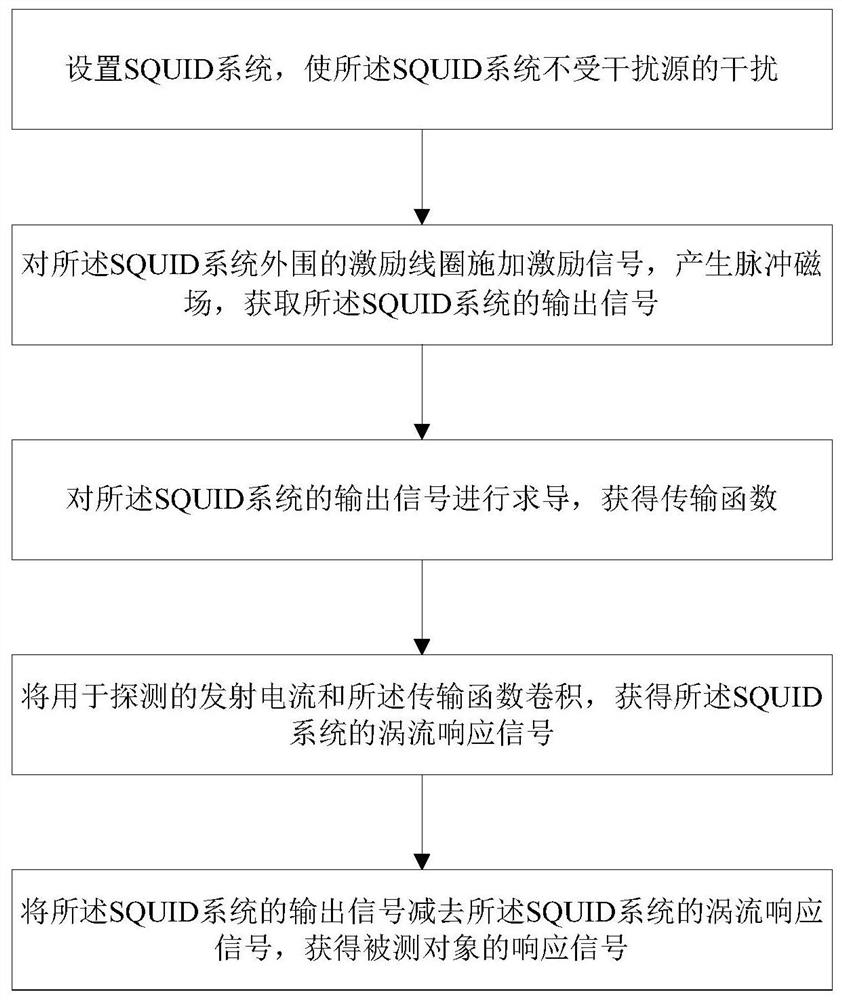
[0063] Such as figure 2 As shown, the present invention provides a kind of eddy current compensation method, and described eddy current compensation method comprises:

[0064] 1) Setting the SQUID system 12 so that the SQUID system 12 is not interfered by interference sources.

[0065] Specifically, in this embodiment, an insulating support 11 is built, and the insulating support 11 is arranged at a place away from interference sources, and the interference sources include but not limited to the earth's magnetic field, power frequency noise or metal objects. Wherein, the SQUID system 12 is kept away from the interference of the earth's magnetic field by setting the height of the insulating support 11, and the SQUID system 12 is kept away from power frequency noise or metal objects, etc. by selecting the geographic location where the insulating support 11 is set. Power frequency noise includes but is not limited to wires placed near the insulating support (away from power fre...

Embodiment 3

[0080] This embodiment provides an eddy current compensation method, which is different from the second embodiment in that this embodiment also compensates the eddy current of a single-sided conductive metal film.

[0081] Specifically, when the periphery of the SQUID system 12 is covered with a multi-layer single-sided conductive metal film: 2) the SQUID system 12 detects the response signal of the measured object, the eddy current response signal of the SQUID system 12 and the The eddy current response signal of the single-sided conductive metal film (three response signals are mixed together); 4) after the convolution operation, the eddy current response of the SQUID system 12 and the eddy current response signal of the single-sided conductive metal film are obtained; 5 ) to subtract the eddy current response signal of the SQUID system 12 and the eddy current response signal of the single-sided conductive metal film from the output signal of the SQUID system 12 to obtain the...


PUM


Abstract

The invention provides an eddy current compensation method and an eddy current compensation system. The method comprises the steps that a SQUID system is undisturbed by an interference source; an excitation signal is applied to an excitation coil in the periphery of the SQUID system to acquire an output signal of the SQUID system; the output signal of the SQUID system is derived to acquire a transfer function; emission current and the transfer function are convolved to acquire an eddy current response signal of the SQUID system; and the eddy current response signal of the SQUID system is subtracted from the output signal of the SQUID system to acquire a response signal of a measured object. The SQUID system is arranged on an insulating bracket. The excitation coil sleeves the SQUID systemto generate a pulsed magnetic field. An arithmetic unit is connected with the output end of the SQUID system to carry out eddy current compensation operation. According to the invention, the solutionmethod of the transfer function of the system is simple; the SQUID has large bandwidth and good response to a pulse signal; the eddy current of the system can be compensated; and the eddy current of an aluminum foil wrapped around the SQUID can be compensated; and the system stability is greatly enhanced.

Description

technical field [0001] The invention relates to the field of magnetic detection, in particular to an eddy current compensation method and an eddy current compensation system. Background technique [0002] Superconducting Quantum Interference Device (hereinafter referred to as SQUID) is the most sensitive magnetic sensor known at present, and the sensitivity of low-temperature superconducting SQUID can reach 1fT (1fT=10 -15 Tesla) level, high-temperature superconducting SQUID sensitivity can also reach 10fT level, is an important high-end application magnetic sensor, widely used in biomedical, geophysical detection, and basic research and other fields. [0003] Transient electromagnetic method is one of the most widely used exploration methods in geophysical exploration. Based on electrical differences, it transmits bipolar pulse signals and receives underground responses. It is mainly used to find low-resistance targets and has high resistance. Jamming capability and resolu...

Claims


Application Information

Patent Timeline
Patent Type & Authority Patents(China)
IPC IPC(8): G01V3/10G01V3/38
CPCG01V3/10G01V3/38
Inventor 包苏新荣亮亮裴易峰伍俊邱隆清谢晓明张懿
Owner SHANGHAI INST OF MICROSYSTEM & INFORMATION TECH CHINESE ACAD OF SCI
Learn More