A detection device and method for environmental test stability of a camera device

A technology for camera devices and environmental testing, which is used in measurement devices, optical instrument testing, machine/structural component testing, etc. Effect

Inactive Publication Date: 2019-10-29
XI'AN INST OF OPTICS & FINE MECHANICS - CHINESE ACAD OF SCI +1
View PDF5 Cites 0 Cited by
  • Summary
  • Abstract
  • Description
  • Claims
  • Application Information

AI Technical Summary

Problems solved by technology

[0004] The purpose of the present invention is to provide a test method for the stability of the camera device environment test, which solves the problem of low work efficiency due to the complicated adjustment process and high environmental requirements in the prior art

Method used


Image

  • A detection device and method for environmental test stability of a camera device
  • A detection device and method for environmental test stability of a camera device
  • A detection device and method for environmental test stability of a camera device

Examples


Embodiment Construction

[0038] The present invention will be described in detail below in conjunction with the accompanying drawings and specific embodiments.

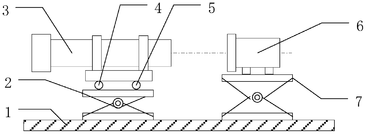
[0039] A detection device for the environmental test stability of an imaging device of the present invention, such as figure 1 As shown, it includes an optical table 1, a shear frame I2 and a shear frame II7 are installed at intervals on the optical table 1, a PSD autocollimator 3 is placed on the shear frame I2, and a camera device 6 is placed on the shear frame II7 to adjust the shear The heights of the frame I2 and the shear frame II7 control the optical axis of the PSD autocollimator 3 to be equal to the optical axis of the camera device 6 .

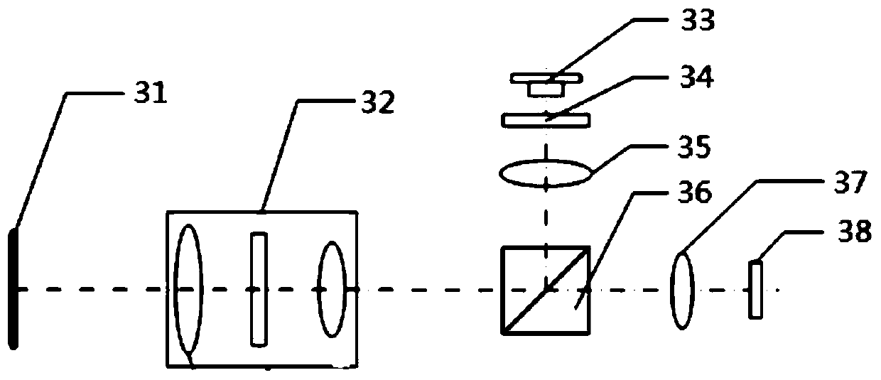
[0040] Such as figure 2 As shown, the PSD autocollimator 3 includes a target reflection surface 31, a telescopic lens group 32, a light source 33, a focusing lens 35, a dichroic prism 36, a converging lens 37 and a PSD chip 38, and the focal point of the converging lens 37 and the light source 33 ...


PUM


Abstract

The invention discloses a method for detecting the environmental test stability of a camera unit. A detecting device including an optical platform is installed; a shearing frame I and a shearing frameII are installed on the optical platform at an interval; a PSD self-collimator is arranged on the shearing frame I and a camera unit is arranged on the shearing frame II; the heights of the shearingframe I and the shearing frame II are adjusted and the optical axis of the PSD self-collimator is controlled to be at the same height as the optical axis of the camera unit; the optical axis positionsof the self-collimator and the camera unit are adjusted to ensure that the deviation angle of the self-collimator is zero; and then the camera unit collects an image of the self-collimator and determines the location of the image of a cross reticle in the image, the locations of the images of the cross reticle in the images before and after testing are compared, and the stability of the camera unit after prescribed environmental test is determined. The detection method has advantages of simple structure, convenient adjustment; and rapid building and measurement at the test site are realized conveniently; and the environmental impact factor is small.

Description

technical field [0001] The invention belongs to the technical field of photoelectric testing, and relates to a detection device for the environmental test stability of an imaging device, and also relates to a detection method for the environmental test stability of the imaging device. Background technique [0002] With the continuous expansion of the application field of CCD imaging devices, more stringent requirements have been put forward for the use environment they can withstand. It is hoped that they can withstand harsh conditions such as shock, vibration, high and low temperature, and improve stability and reliability. In order to verify whether the optomechanical structure and CCD focal plane structure of the CCD imaging device have changed after various environmental tests, so as to provide a reference for further performance testing, it is necessary to adopt a certain test method to compare the optomechanical structure with the CCD focal plane structure. Changes in ...

Claims


Application Information

Patent Timeline
Patent Type & Authority Patents(China)
IPC IPC(8): G01M11/00
CPCG01M11/00
Inventor 昌明赵建科周艳乔卫东郭梁王争锋薛勋李晶巩立李跃
Owner XI'AN INST OF OPTICS & FINE MECHANICS - CHINESE ACAD OF SCI
Why Eureka
Try Eureka