
Absorption/contraction mixing circulatory system for independent mechanical cooling

A mechanical cooling and circulation system technology, applied in refrigerators, refrigeration and liquefaction, lighting and heating equipment, etc., can solve the problems of system heating capacity and COP decrease, compressor discharge temperature rise, compressor discharge temperature high, etc. Achieve the effect of improving system heating COP and reducing power consumption

Inactive Publication Date: 2019-04-16
TONGJI UNIV
View PDF4 Cites 2 Cited by
  • Summary
  • Abstract
  • Description
  • Claims
  • Application Information

AI Technical Summary

Problems solved by technology

[0003] For the mechanical vapor compression refrigeration / heat pump cycle, currently limited by factors such as refrigerant, cycle and components, the energy efficiency and operating range of the system are limited to a certain extent
The maximum water supply temperature is generally lower than 90°C, and it is difficult to break through 100°C
Because of the high condensing temperature, the compressor is overloaded, causing the discharge temperature of the compressor to be too high, and even causing the compressor to stop. At the same time, the heating capacity and COP of the system also drop sharply.
For the production of hot water or steam above 100°C, the current relatively mature heat pump technology is the second type of absorption heat pump, but it needs to be driven by a medium-temperature heat source (waste hot water at 80°C), and its scope of application is very limited.
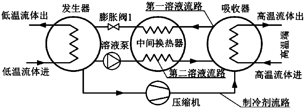
In addition, in order to improve the COP of the current heat pump cycle, researchers proposed an absorption / compression hybrid cycle, such as figure 1 As shown, it is called the first absorption / compression hybrid cycle. However, for this cycle, when operating under high temperature heating conditions (heating temperature is greater than 100°C), the discharge temperature of the compressor will increase significantly, and it is difficult to select a suitable the compressor

Method used


Image

  • Absorption/contraction mixing circulatory system for independent mechanical cooling
  • Absorption/contraction mixing circulatory system for independent mechanical cooling

Examples


Embodiment

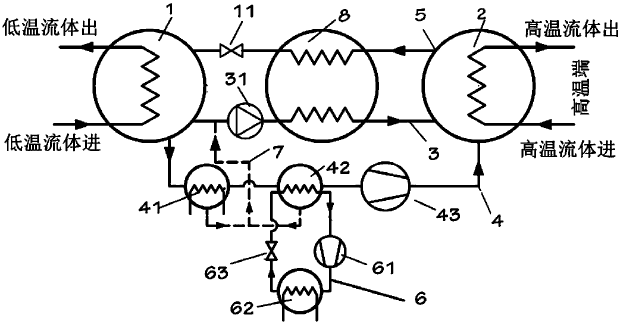
[0020] Separate mechanically cooled absorption / compression hybrid cycle comprising generator 1, absorber 2 and vapor compression cycle 6, see figure 2 .

[0021] The generator 1 includes the first heat exchange channel of the generator and the second heat exchange channel of the generator, the absorber 2 includes the first heat exchange channel of the absorber and the second heat exchange channel of the absorber, and the first heat exchange channel of the generator The heat exchange channel is used to absorb heat from the low temperature end and transfer the heat to the second heat exchange channel of the absorber, and a second solution flow path is provided between the second heat exchange channel of the generator and the second heat exchange channel of the absorber 3. Refrigerant flow path 4 and first solution flow path 5, see figure 2 , the second heat exchange channel of the generator is used for the evaporation of the concentrated refrigerant solution to generate a dil...


PUM


Abstract

The invention relates to an absorption / contraction mixing circulatory system for independent mechanical cooling. The absorption / compression mixing circulatory system comprises a generator (1), an absorber (2) and a vapor compression cycle (6), wherein a second solution flow path (3), a refrigerant flow path (4) and a first solution flow path (5) are arranged between the second heat exchange channel of the generator (1) and the second heat exchange channel of the absorber (2); the refrigerant flow path (4) is provided with a first cooler (41) and a second cooler (42), wherein a second cooler second heat exchange channel is connected with the vapor compression cycle (6), the vapor compression cycle (6) sequentially comprises a second compressor (61), a condenser (62) and a second expansion valve (63) which are arranged in series. Compared with the prior art, the air suction temperature of the compressor is cooled step by step, the power consumption of the compressor can be reduced as well, and then the heating COP of the system is improved.

Description

technical field [0001] The invention relates to the technical field of heat pump equipment, in particular to an absorption / compression mixed cycle system with independent mechanical cooling. Background technique [0002] With the rapid development of the global economy and the increasingly serious energy crisis and environmental pollution, it is urgent to develop efficient and clean heat extraction technologies. As a new way of heat extraction, heat pumps have attracted widespread attention due to their advantages such as high energy efficiency and simple structural features. At present, the more mature heat pump technologies are mechanical vapor compression heat pump technology and absorption heat pump technology. [0003] For the mechanical vapor compression refrigeration / heat pump cycle, currently limited by factors such as refrigerant, cycle, and components, the energy efficiency and operating range of the system are limited to a certain extent. The maximum water suppl...

Claims


Application Information

Patent Timeline
Patent Type & Authority Applications(China)
IPC IPC(8): F25B25/02
CPCF25B25/02
Inventor 邵亮亮高鹏常萌萌张春路
Owner TONGJI UNIV
Learn More