
A compressor exhaust muffler

A compressor exhaust and muffler technology, applied in the field of compressors, can solve problems such as unfavorable compressor service life, reduced compressor efficiency, motor burn-in, etc., to reduce internal temperature, reduce heat exchange, and improve service life Effect

Inactive Publication Date: 2017-10-31
GUANGDONG POLYTECHNIC NORMAL UNIV
View PDF6 Cites 0 Cited by
  • Summary
  • Abstract
  • Description
  • Claims
  • Application Information

AI Technical Summary

Problems solved by technology

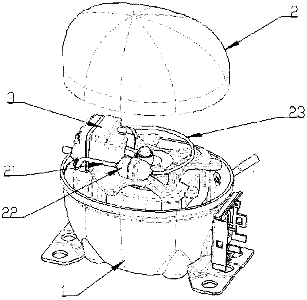
Under such circumstances, a large amount of heat from the exhaust muffler (22) remains inside the compressor and is not discharged outside the compressor, which increases the suction temperature of the compressor and reduces the efficiency of the compressor
At the same time, due to the high internal temperature of the compressor, it is easy to cause the motor to burn out, which is not conducive to protecting the service life of the compressor

Method used


Image

  • A compressor exhaust muffler
  • A compressor exhaust muffler
  • A compressor exhaust muffler

Examples


Embodiment Construction

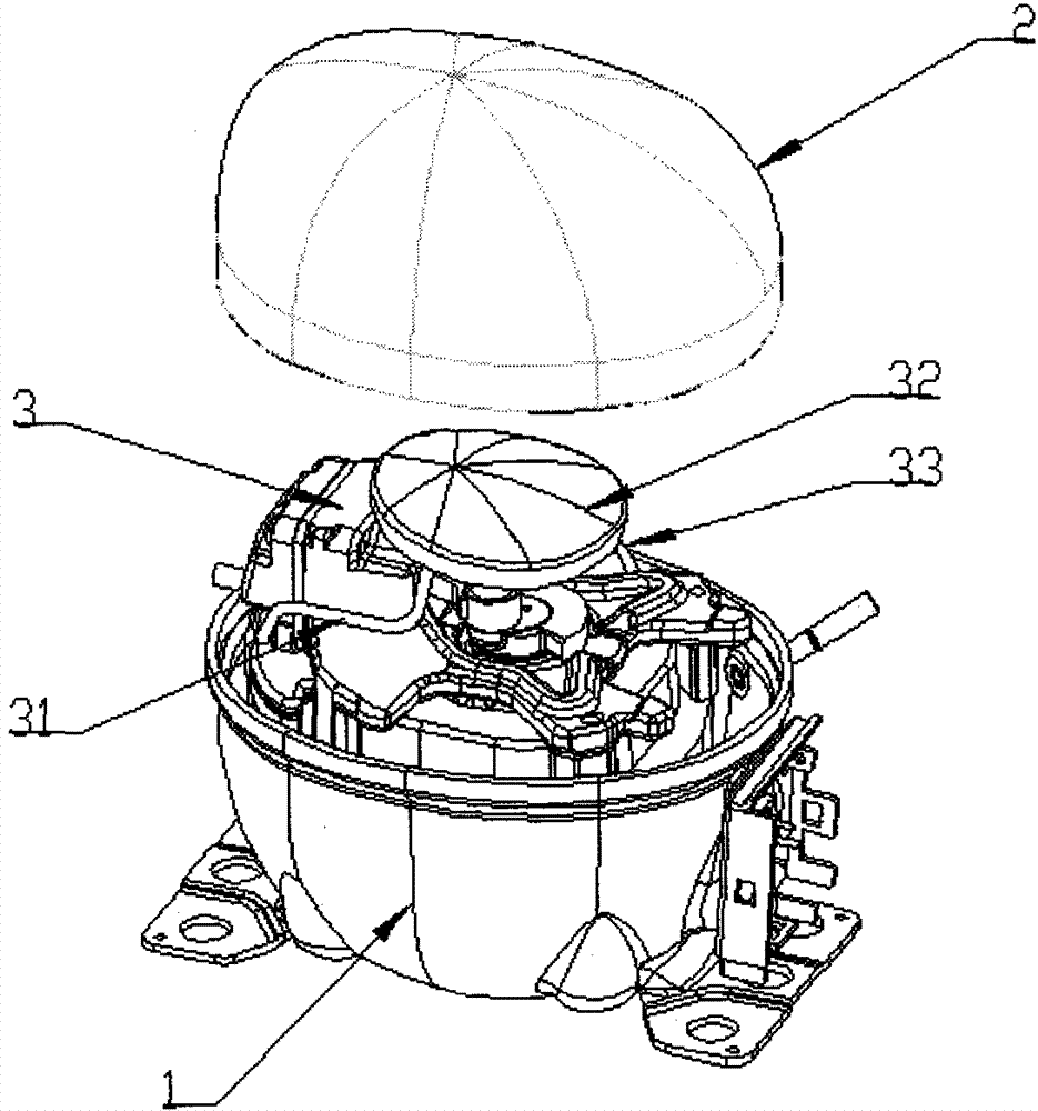
[0016] refer to Figure 1 to Figure 5 , the invention provides a compressor exhaust muffler, comprising a cavity (32) provided with an air intake line (31) and an exhaust line (33), the cavity (32) is connected to the air intake line (31) A muffler cavity is formed between the exhaust pipeline (33), and the cavity (32) is sealed and formed by a thin-walled metal material with a certain thickness. The cavity (32) is installed in the compressor shell, and the shell includes an upper shell (2) and lower shell (1).

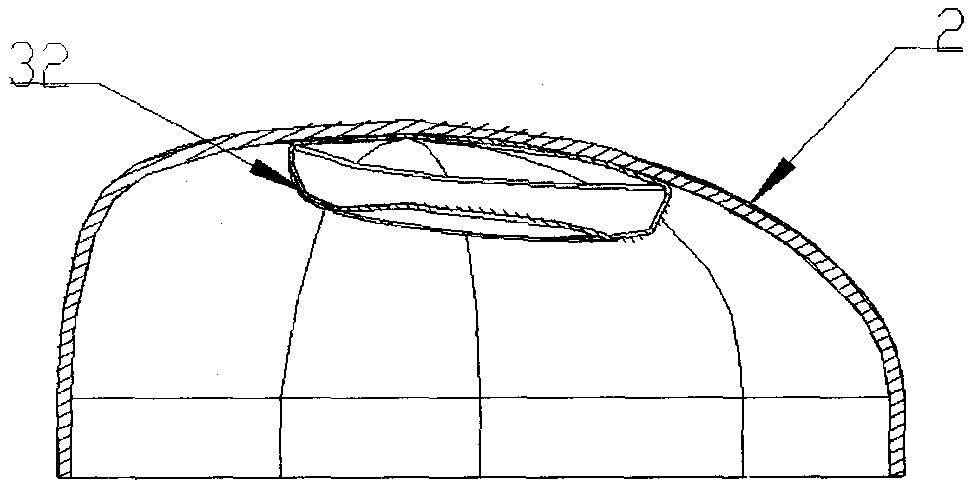
[0017] In the compressor exhaust muffler, the cavity (32) is installed on the inner surface of the upper end of the upper shell (2), and the shape of the upper surface of the cavity (32) is similar to that of the inner surface of the upper shell (2). After installation, the upper surface of the cavity (32) is completely attached to the inner surface of the upper shell (2). The high temperature of the cavity (32) is directly transmitted to the upper shell (2). Since...


PUM


Abstract

The invention discloses a compressor exhaust muffler, which is used in the field of compressors, comprising a cavity (32) provided with an intake pipeline (31) and an exhaust pipeline (33), and the cavity (32) is connected to the intake pipeline. (31) and the exhaust pipeline (33) form a muffler cavity, and the cavity (32) is formed by sealing a thin-walled metal material with a certain thickness, and the cavity (32) is installed in the compressor shell, and the shell It includes an upper shell (2) and a lower shell (1). In the compressor exhaust muffler, the cavity (32) is installed on the inner surface of the upper end of the upper shell (2), and the shape of the upper surface of the cavity (32) is similar to that of the inner surface of the upper shell (2). After installation, the upper surface of the cavity (32) is completely attached to the inner surface of the upper shell (2). The heat of the exhaust muffler cavity (32) is transferred to the upper shell (2), and is quickly transferred to the environment through the upper shell (2). The present invention reduces the temperature inside the compressor through such a design.

Description

technical field [0001] The invention is used in the field of compressors, in particular to a compressor exhaust muffler. Background technique [0002] The traditional compressor is equipped with an exhaust muffler (22), which is connected to the core (3) through the intake pipeline (21), and connected to the lower shell (1) through the exhaust pipeline (23), forming an air flow path for exhaust , to play the role of the exhaust muffler. When the compressor is running, it compresses the gas. After the gas is compressed, the temperature rises sharply, resulting in a high discharge temperature, while the gas temperature inside the compressor shell is lower, forming a temperature gradient. The exhaust muffler (22) transfers a large amount of heat to the gas inside the compressor through heat transfer, natural convection and other means. Simultaneously, because the position of the exhaust muffler (22) is relatively low, the refrigerating machine oil splashed during compressor ...

Claims


Application Information

Patent Timeline
Patent Type & Authority Patents(China)
IPC IPC(8): F04B39/00
Inventor 叶子波罗忠辉李玉忠徐伟陈森昌李冬梅
Owner GUANGDONG POLYTECHNIC NORMAL UNIV
Learn More