
High-liquid limit soil reinforcement roadbed filling structure and method

A high liquid limit soil and filling technology, applied in roads, roads, buildings, etc., can solve the problems of poor stability, low strength, high water content, etc., and achieve improved modulus of resilience, obvious skeleton effect, and soil permeability enhanced effect

Pending Publication Date: 2019-04-16
NO 3 ENG COMPANY LTD OF CCCC FIRST HARBOR ENG COMPANY +1
View PDF0 Cites 3 Cited by
  • Summary
  • Abstract
  • Description
  • Claims
  • Application Information

AI Technical Summary

Problems solved by technology

[0002] High liquid limit soil, high water content, light bulk density, poor stability, low strength, according to the conventional construction process, the degree of compaction cannot meet the requirements of the design specification

Method used


Image

  • High-liquid limit soil reinforcement roadbed filling structure and method
  • High-liquid limit soil reinforcement roadbed filling structure and method

Examples


Embodiment 1

[0024] In this embodiment, the application section is Wanyang Expressway K110+200 to K110+500, the maximum filling height of this section is 7.1m, and the minimum is 6.2m.

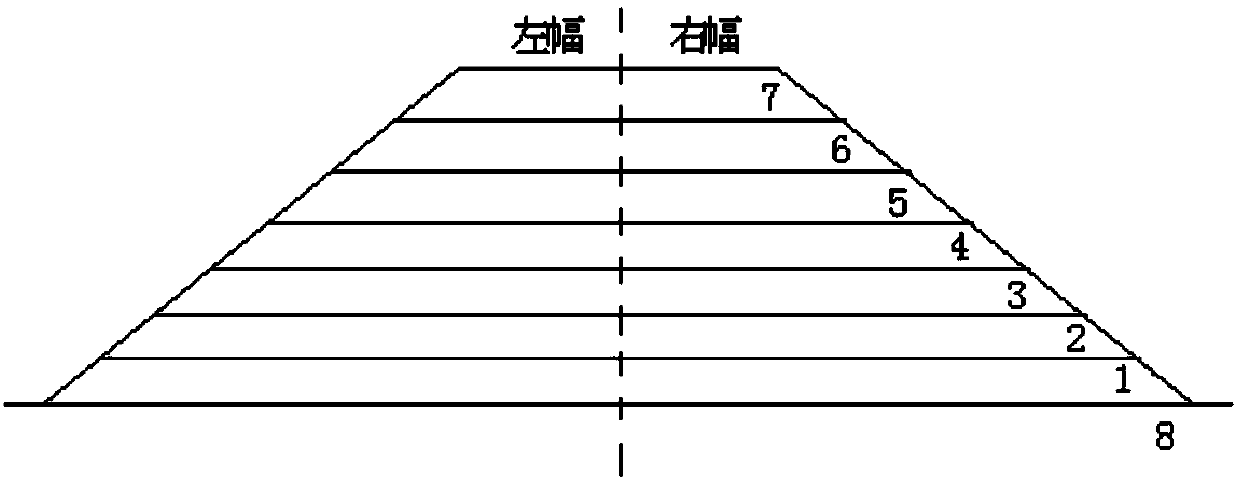
[0025] like figure 1 , 2 As shown, a high liquid limit soil reinforced roadbed filling structure, the filling structure includes 93 areas, 94 areas and 96 areas arranged in sequence from bottom to top, and each area is divided into a left side and a right side by the center line of the cross section. ; Described 94 area includes 94-1 layer 1, 94-2 layer 2 and 94-3 layer 3 arranged sequentially from bottom to top, and described 96 area includes 96-1 layer 4, 96-2 arranged sequentially from bottom to top Layer 5, 96-3 Layer 6 and 96-4 Layer 7.

[0026] The thickness of the 93 area (8) is 5100mm, the thickness of each layer in the 94 area is 94-1 layer (1) 300mm, 94-2 layer (2) 200mm, 94-3 layer (3) 200mm, the said The thickness of each layer in the 96 area is 96-1 layer (4) 200mm, 96-2 layer (5) 200mm, 96...

Embodiment 2

[0030] Using a high liquid limit soil reinforced roadbed filling method of the filling structure described in Example 1, the construction road section is divided into sections and layers to form a roadbed filling structure. Liquid-limited soil or low-liquid-limited soil mixed with different proportions of gravel or cement at the same time, including the following steps:

[0031] S1. Divide the construction road section into zone-layer structure to form a subgrade filling structure. The filling structure includes zone 93, zone 94 and zone 96 arranged in sequence from bottom to top, and each zone is divided into the left side by the center line of the cross section. and the right panel; the 94 area includes 94-1 layer 1, 94-2 layer 2 and 94-3 layer 3 arranged in sequence from bottom to top, and the 96 area includes 96-1 layer 4, 96-1 layer 4, 96-2 floor 5, 96-3 floor 6 and 96-4 floor 7;

[0032] S2. Fill each layer of each location, and the specific filling composition of each ...


PUM


Abstract

The invention relates to the field of road construction, in particular to a high-liquid limit soil reinforcement roadbed filling structure and method. The filling method comprises the steps that a construction road is divided according to a section layer structure, the roadbed filling structure is formed, each layer is filled with high-liquid limit soil or low-liquid limit soil of different components, and meanwhile each layer is doped with gravel or cement with different proportions; the filling structure comprises a 93 area, a 94 area and a 96 area which are arrayed from bottom to top in sequence, and each area is divided into a left piece and a right piece according to the center line of a cross section; the 94 area comprises a 94-1 layer, a 94-2 layer and a 94-3 layer which are arrayedfrom bottom to top in sequence, and the 96 area comprises a 96-1 layer, a 96-2 layer, a 96-3 layer and a 96-4 layer which are arrayed from bottom to top in sequence. The filling structure is suitablefor roadbed filling through a wet method, strength reinforcement of a road section is needed, the design and construction demand is met, so that the soil body forms the compact sandy soil body structure, the formwork function of coarse particles is obvious, and the CBR, compaction degree, resilience modulus and other indexes are obviously increased.

Description

technical field [0001] The invention relates to the field of road construction, in particular to a high liquid limit soil reinforced roadbed filling structure and method. Background technique [0002] High liquid limit soil, high water content, light bulk density, poor stability and low strength, the compaction degree according to the conventional construction process cannot meet the requirements of the design specification. Soil with high liquid limit generally refers to soil with liquid limit greater than 50% and plasticity index greater than 26. On the contrary, it is soil with low liquid limit. How to scientifically and fully utilize the high liquid limit soil to fill the roadbed under some rainy weather conditions, ensure the quality and progress of the project, save resources and protect the environment, is a major engineering technical problem that urgently needs to be solved in some construction projects. SUMMARY OF THE INVENTION [0003] In order to solve the abo...

Claims


Application Information

Patent Timeline
Patent Type & Authority Applications(China)
IPC IPC(8): E01C3/00E01C3/04
CPCE01C3/00E01C3/04
Inventor 薛孝维吴飞刘周礼孙运波潘滢
Owner NO 3 ENG COMPANY LTD OF CCCC FIRST HARBOR ENG COMPANY
Learn More