A sand-adding sedimentation tank for realizing efficient sludge discharge

A sedimentation tank, high-efficiency technology, applied in sedimentation separation, sedimentation tank, sediment separation by centrifugal force, etc., can solve the problems of low sludge discharge efficiency, high investment cost, easy torque overload, etc., to improve sludge discharge efficiency and investment cost. Low, reduced usage effect

Active Publication Date: 2021-09-24
北京翰祺环境技术股份有限公司
View PDF12 Cites 1 Cited by
  • Summary
  • Abstract
  • Description
  • Claims
  • Application Information

AI Technical Summary

Problems solved by technology

[0004] The above-mentioned existing technical solutions have the following defects: (1) The flocculation water inlet method is single, and the reaction between the chemical agent and the sewage in the flocculation area is insufficient, resulting in poor flocculation effect; (2) The sludge is gradually scraped from the periphery by a sludge scraper To the central sludge collection tube of the pool, when the designed sludge layer is thick, it is necessary to consider a sludge scraper with a larger torque to scrape the sludge to the central sludge collection tube, which requires higher energy consumption and lower investment costs. It will increase accordingly, and it is easy to overload the torque, which will cause damage to the sludge scraper; (3) When the designed sludge layer is thin, the sludge discharged from the sedimentation tank will have a low concentration, a large amount of sludge, and a low efficiency of sludge discharge per unit time. The sand-adding sedimentation tank is matched with a large-capacity sludge tank, and the investment cost is high

Method used


Image

  • A sand-adding sedimentation tank for realizing efficient sludge discharge
  • A sand-adding sedimentation tank for realizing efficient sludge discharge
  • A sand-adding sedimentation tank for realizing efficient sludge discharge

Examples


Embodiment 2

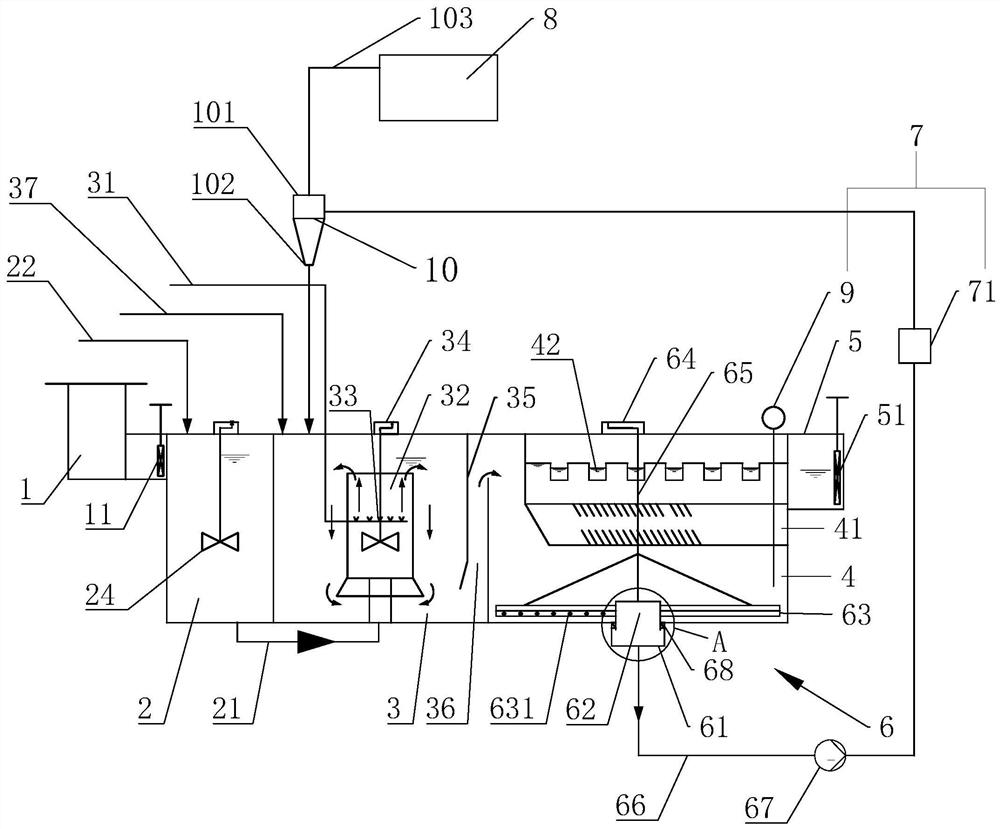
[0061] Referring to Fig. 6, the difference between the present embodiment and the first embodiment is that a water weir is provided between the coagulation area 2 and the flocculation area 3, and the water weir is a shared room wall of two adjacent areas, and the shared The top of the chamber wall is lower than the tank top level, so that the coagulation zone 2 and the flocculation zone 3 are connected. In the coagulation zone 2, a first baffle 25 is vertically arranged, and the lower end of the first baffle 25 is at the bottom of the coagulation zone 2. Above, a water passage is formed between the lower end of the first baffle plate 25 and the bottom of the coagulation zone 2, through which the sewage from the water distribution well 1 can enter the coagulation zone 2, thereby preventing short flow of sewage.

[0062] Wherein, a coagulant adding pipe 22 for adding coagulant is connected between the second baffle plate and the water inlet gate 11 in the coagulation area 2 . A ...


PUM


Abstract

The invention relates to a sand-adding sedimentation tank for realizing high-efficiency mud discharge, which includes a water distribution well, a coagulation area, a flocculation area, a sedimentation separation area and an outlet channel connected in sequence along the sewage flow direction, and the sedimentation separation area is also equipped with There is a mud suction device and a mud level control device for monitoring and controlling the thickness of the sludge at the bottom of the sedimentation separation area; The mud collection tube with the rotation of the mud hole, two suction main pipes symmetrically connected to the outer peripheral wall of the mud collection tube along the central axis of the mud collection tube, the mud discharge pipe connected to the bottom of the mud discharge hole, and the mud discharge pipe connected The dredging pump and the motor used to drive the mud collecting tube to rotate; the mud collecting tube communicates with the mud discharge hole, the side of the dredging main pipe facing the bottom of the sedimentation separation area has a side edge, and the dredging main pipe is provided with Round suction hole. The invention has the effects of low energy consumption, high mud discharge concentration and high mud discharge efficiency per unit time.

Description

technical field [0001] The invention relates to the technical field of water supply and municipal sewage treatment, in particular to a sand-adding sedimentation tank for realizing efficient mud discharge. Background technique [0002] The high-efficiency sedimentation tank integrates various separation theories such as chemical coagulation, flocculation, sludge return, inclined tube separation, and sludge concentration. It has high-speed water separation and synchronous sludge development through reasonable hydraulic design and structural combination. A new generation of precipitation process with concentration function. [0003] The Chinese patent with the publication number CNU discloses a new type of high-speed and high-efficiency sedimentation tank for adding sand, which includes a rectangular structure and a partition wall. pool; the bottom of the coagulation tank is provided with a water inlet pipe and a flocculant dosing pipe, the middle is provided with a mixer, and...

Claims


Application Information

Patent Timeline
Patent Type & Authority Patents(China)
IPC IPC(8): B01D21/01B01D21/02B01D21/24B01D21/26
CPCB01D21/01B01D21/02B01D21/245B01D21/26
Inventor 王晓阳汪德罡谢晓朋
Owner 北京翰祺环境技术股份有限公司
Why Eureka
Try Eureka