
Working mode analysis method of complex power electronic converter

A technology of power electronics and working modes, which is applied in the direction of adjusting electrical variables, converting DC power input to DC power output, and instruments, can solve problems such as large amount of calculation, complex calculation of matrix modulus, complex combination, etc., to reduce analysis The effects of difficulty, comprehensive analysis results, and simple analysis process

Active Publication Date: 2019-04-12
SOUTH CHINA UNIV OF TECH
View PDF2 Cites 2 Cited by
  • Summary
  • Abstract
  • Description
  • Claims
  • Application Information

AI Technical Summary

Problems solved by technology

When the power electronic converter contains more switches, the order of the matrix obtained by the generalized connection matrix method is large, and the modulus calculation of the matrix is ​​complicated
The adjacency matrix method uses 0 and 1 to replace the connection between the components. Although the calculation is simplified, it can only represent the connection between the components in the circuit, and cannot directly represent the modes.
In addition, the above two methods analyze the current path and cannot directly obtain the effective mode. In the process of path combination mode, some modes may be missed, resulting in incomplete analysis results.
The switch Boolean matrix method is to directly analyze the working mode of the power electronic converter based on the on-off state of the switch. In this method, all non-switching elements are connected to the circuit in the on-state by default, which will lead to inaccurate identification of the circuit mode. Comprehensive, also has the disadvantage of incomplete analysis results
The mesh combination method uses the "union" and "ring sum" operations between meshes to obtain subcircuits, but these subcircuits contain repeated subcircuits, that is, there are more redundant subcircuits in the analysis process.
At the same time, when the number of meshes is large, the amount of calculation is large, and the number of repeated sub-circuits also increases accordingly.
Using computer-aided analysis software to analyze the circuit mode, the effective path is obtained through deep search, but there is no clear method for the combination relationship between the paths, and the effective mode cannot be obtained directly. When there are many effective paths, the combination is complicated.

Method used


Image

  • Working mode analysis method of complex power electronic converter
  • Working mode analysis method of complex power electronic converter
  • Working mode analysis method of complex power electronic converter

Examples


Embodiment Construction

[0031] The present invention will be further described below in conjunction with specific examples.

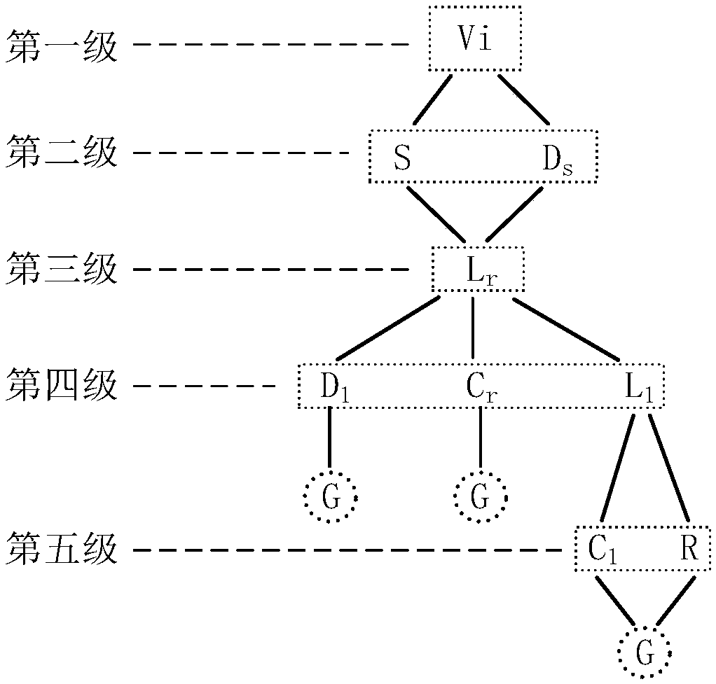
[0032] Such as figure 1 As shown, the working mode analysis method of the complex power electronic converter provided in this embodiment includes the following steps:

[0033] 1) Draw each component in the power electronic converter into the tree diagram according to the sequence of current flow, wherein, according to the sequence of current flow, it means starting from the power supply, drawing all the components in the circuit into the tree diagram in sequence, in When drawing a tree diagram, it is assumed that each component in the circuit has a specific one-way conductivity, that is, regardless of the current flow direction of the actual component, it is set to start from the positive pole of the power supply, flow through each component without a return path, and finally flow to then the branch ends.

[0034] 2) The components in the tree diagram are divided into differ...


PUM


Abstract

The invention discloses a working mode analysis method of a complex power electronic converter. The working mode analysis method comprises the following steps that 1) elements contained in the converter are drawn into a tree diagram; 2) the elements in the tree diagram are classified into different grades; 3) the on-off state combinations possibly existing in all the switching elements in each stage are listed; 4) the on-off state combinations in each stage are overlapped with non-switching elements respectively; 5) different grades of elements are overlapped, and a new mode is obtained aftereach superposition is carried out; 6) screening is carried out on the model states, and invalid modes are removed; and 7) the effective modes are combined according to the actual current flowing condition, and the types of the effective working modes of the converter are obtained. All the working modes of the electric power electronic converter can be obtained, and the recognition of the modes iscomprehensive and simple, so that the method can be used for analyzing a circuit mode of a multi-switch power electronic converter.

Description

technical field [0001] The invention relates to the technical field of effective working mode identification of power electronic converters, in particular to a working mode analysis method of complex power electronic converters. Background technique [0002] The modal analysis for power electronic converters can effectively identify all effective working modes of power electronic converters in the actual working process, including normal working modes and potential circuit modes of power electronic converters. Because there are many switching devices in the power electronic system, it is very difficult to identify the circuit mode. Therefore, it is necessary to study a set of modal analysis methods suitable for identifying complex power electronic converters with multiple switches. [0003] At present, the modal analysis methods for power electronic converters mainly include: generalized connection matrix method, adjacency matrix method, switch Boolean matrix method, mesh c...

Claims


Application Information

Patent Timeline
Patent Type & Authority Applications(China)
IPC IPC(8): H02M3/155
CPCH02M3/155
Inventor 丘东元范晓芙张波陈艳峰
Owner SOUTH CHINA UNIV OF TECH
Learn More