Shock-absorbent power-wasting three-way limiting metal damping device for near-fault bridge and mounting method thereof

A metal damping and damping device technology, used in bridges, bridge construction, bridge parts, etc., can solve problems such as the inability to identify the speed change value of the main beam, the failure of the limiter function of the damper, and the shock damage of the upper main beam falling beam. Good ductility deformation, ensure normal use, and dissipate seismic energy

Active Publication Date: 2019-04-12
CHINA RAILWAY ERYUAN ENG GRP CO LTD
View PDF24 Cites 1 Cited by
  • Summary
  • Abstract
  • Description
  • Claims
  • Application Information

AI Technical Summary

Problems solved by technology

[0004] The purpose of the present invention is to overcome the problems existing in the prior art, that is, the existing bridge damper cannot identify the speed change value of the main girder when the train crosses the bridge, so it cannot play the role of damping limit, that is, the limit of the damper. The position function will fail, and at the same time, the vertical seismic intensity is relatively large in the near-field earthquake, and the upper main girder is prone to the above-mentioned shortcomings of falling beam earthquake damage. A kind of shock-absorbing and energy-consuming three-way limit metal damping device for near-fault bridges is provided. installation method

Method used


Image

  • Shock-absorbent power-wasting three-way limiting metal damping device for near-fault bridge and mounting method thereof
  • Shock-absorbent power-wasting three-way limiting metal damping device for near-fault bridge and mounting method thereof
  • Shock-absorbent power-wasting three-way limiting metal damping device for near-fault bridge and mounting method thereof

Examples


Embodiment 1

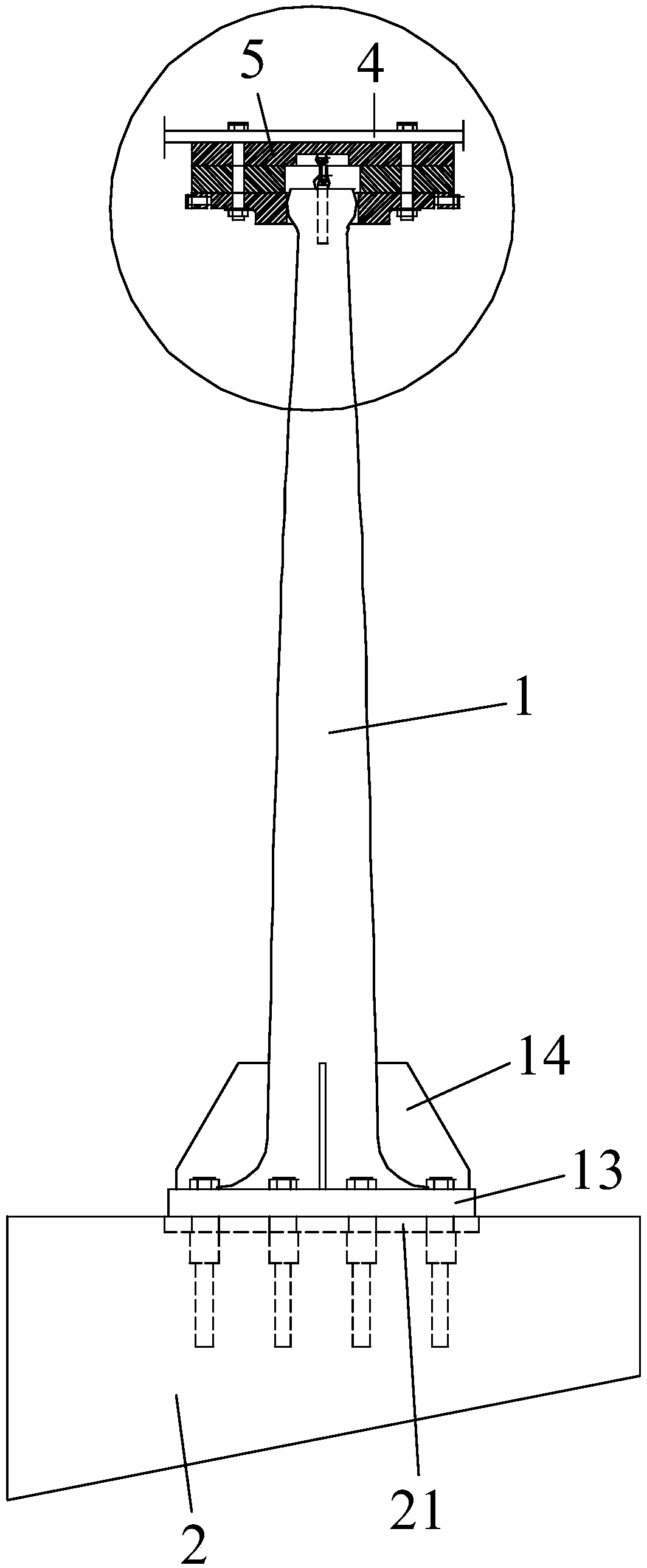
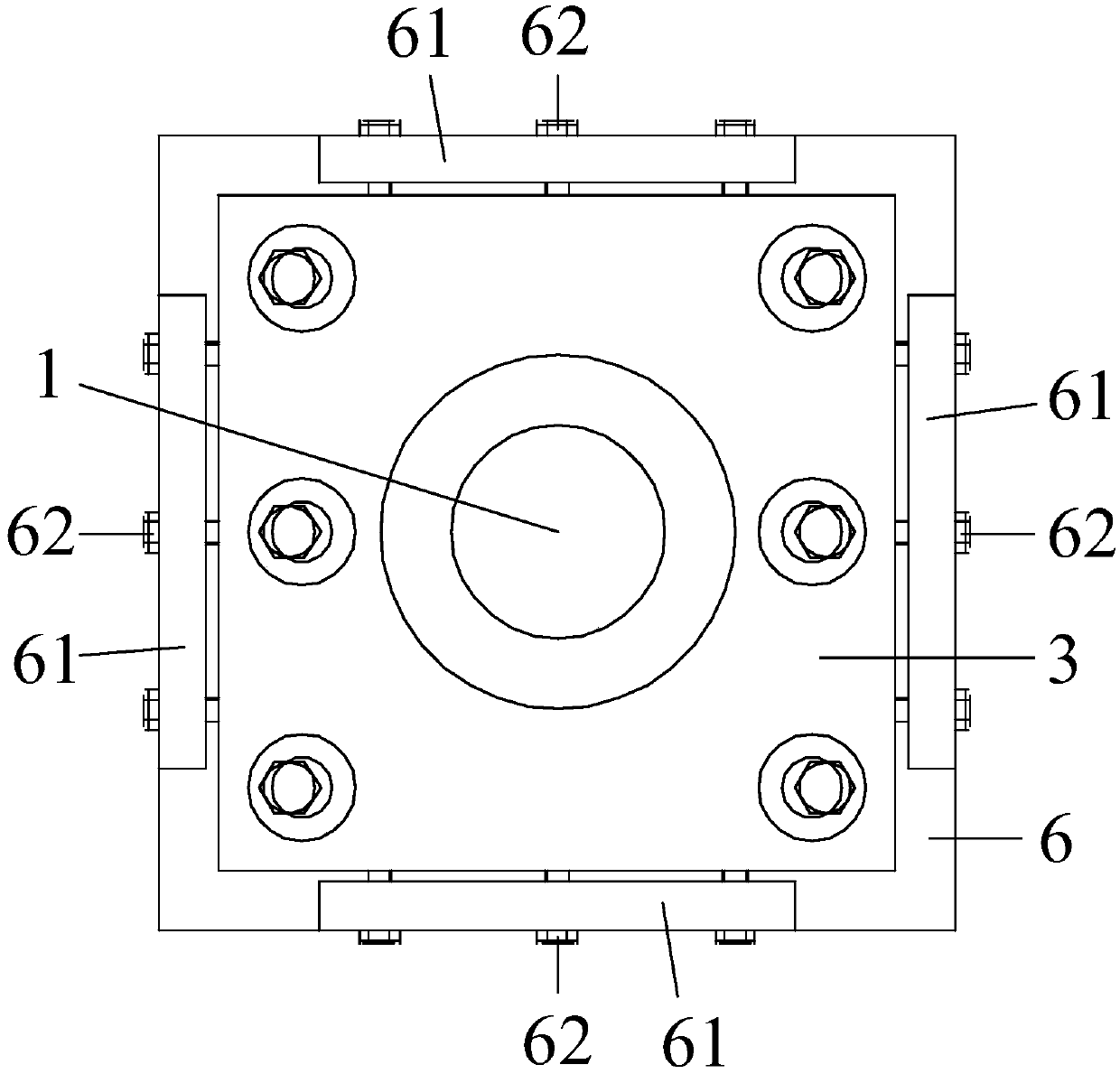
[0056] like Figure 1-4 , Shown in 11-12, a kind of near-fault bridge of the present invention uses shock-absorbing energy-dissipating three-way limit metal damping device, comprises elastic-plastic limit shock-absorbing energy-consuming rod 1 and adjustable connecting plate 3, described The bottom of the elastic-plastic limiting shock-absorbing energy-dissipating rod 1 is connected to the top of the arch rib beam 2, and the adjustable connecting plate 3 is provided with an inner hole.

[0057] The elastic-plastic limiting shock-absorbing energy-dissipating rod 1 is a structural member made of high-ductility special steel, and its sections follow the design principle of "equal-strength beam" along the height direction, that is, by changing the size of the energy-dissipating rod section, the member Entering into yield in a large range at the same time, under the premise of meeting the horizontal stiffness requirements, can ensure the least amount of steel consumption and obtain...

Embodiment 2

[0065] like Figure 5-12As shown, a shock-absorbing energy-dissipating three-way limit metal damping device for a near-fault bridge according to the present invention includes an elastic-plastic limit shock-absorbing energy-dissipating rod 1 and an adjustable connecting plate 3, and the elastic-plastic limit The bottom of the shock-absorbing energy-dissipating rod 1 is connected to the top of the arch rib beam 2, and the adjustable connecting plate 3 is provided with an inner hole.

[0066] The elastic-plastic limiting shock-absorbing energy-dissipating rod 1 is a structural member made of high-ductility special steel, and its sections follow the design principle of "equal-strength beam" along the height direction, that is, by changing the size of the energy-dissipating rod section, the member Entering into yield in a large range at the same time, under the premise of meeting the horizontal stiffness requirements, can ensure the least amount of steel consumption and obtain the...

Embodiment 3

[0075] like Figure 5-12 Shown a kind of installation method of the vibration-absorbing and energy-consuming three-way limit metal damping device for near-fault bridges as described in embodiment 2, comprising the following steps:

[0076] Step 1. A cage is set on the shaft of the elastic-plastic limit shock-absorbing energy-dissipating rod 1, and the lifting lug 11 is screwed into the top of the elastic-plastic limit-damping shock-absorbing energy-dissipating rod 1. The top of the shock-absorbing energy-dissipating rod 1 penetrates the inner hole on the adjustable connecting plate 3, and the adjustable connecting plate 3 is arranged on the cage;

[0077] The lifting lug 11 includes a screw rod, and the top of the elastic-plastic limit shock-absorbing energy-dissipating rod 1 is provided with a screw hole adapted to the screw rod;

[0078] Step 2, setting the backing plate 6 on the adjustable connecting plate 3, and the peripheral edge of the backing plate 6 abuts against the...


PUM


Abstract

The invention discloses a shock-absorbent power-wasting three-way limiting metal damping device for a near-fault bridge and a mounting method thereof. The device comprises an elastic-plastic limitingshock-absorbent power-wasting rod and an adjustable connecting plate, wherein the adjustable connecting plate is provided with an inner hole; each cross section of the elastic-plastic limiting shock-absorbent power-wasting rod can simultaneously enter a yield state to realize maximum ductile deformation; the bottom of the elastic-plastic limiting shock-absorbent power-wasting rod is connected withthe top of a bridge pier, a bridge tower crossbeam or an arch rib crossbeam; the top of the elastic-plastic limiting shock-absorbent power-wasting rod extends into the inner hole, the periphery of the top is abutted against the wall of the inner hole along two opposite sides of a bridge direction, and the separation distance n (n is more than or equal to 0) is reserved between two opposite sidesof a top transverse bridge direction and the wall of the inner hole; the adjustable connecting plate is connected with an upper connecting piece; a lifting lug is arranged at the top of the elastic-plastic limiting shock-absorbent power-wasting rod; the bottom of the upper connecting piece corresponding to the inner hole is provided with an anti-pulling pull ring; a gap is arranged between the topend of the lifting lug and the bottom end of the anti-pulling pull ring; and the anti-pulling pull ring and the lifting lug are connected through an anti-pulling pull cable.

Description

technical field [0001] The invention relates to the field of bridges, in particular to a shock-absorbing and energy-consuming three-way limit metal damping device and an installation method for near-fault bridges. Background technique [0002] In the existing long-span bridge structure, during the running of a high-speed train, the main girder bears a large horizontal force due to the large traction braking force of the train, and the traction braking force will cause a large horizontal displacement of the main girder (especially for fully floating system of medium-supported concrete-filled steel tube arch bridges, long-span steel truss cable-stayed bridges, etc.), excessive displacement will cause rail stretching, and deformation of the main beam caused by the joint action of train traction braking loads and other operating loads (such as temperature loads, etc.) When it is too large, the broken rail will be damaged, which will directly affect the driving safety. Therefore,...

Claims


Application Information

Patent Timeline
Patent Type & Authority Applications(China)
IPC IPC(8): E01D19/00E01D21/00
CPCE01D19/00E01D21/00Y02A30/30
Inventor 董俊曾永平陈克坚李聪林庞林户东阳游励晖郑晓龙陈长征杨国静陶奇苏延文徐昕宇周川江颜永逸周昆保亮
Owner CHINA RAILWAY ERYUAN ENG GRP CO LTD
Why Eureka
Try Eureka