Automatic cloth leftover winding device

A winding device and automatic technology, which is applied in winding strips, transportation and packaging, thin material processing, etc., can solve the problems of potential safety hazards, long downtime, high labor costs, etc., to reduce labor costs, shorten downtime, The effect of reducing operational accidents

Pending Publication Date: 2019-04-12
CHANGSHA CTR ROBOTICS
View PDF0 Cites 0 Cited by
  • Summary
  • Abstract
  • Description
  • Claims
  • Application Information

AI Technical Summary

Problems solved by technology

[0002] Domestic toilet paper rewinding machines, etc., have relatively soft paper heads, which can be pasted on the inflatable shaft by blowing air from the nozzle to realize automatic winding, but this method is only suitable for relatively soft materials
For non-woven materials with a certain hardness, the blowing device cannot wrap them on the inflatable shaft
Therefore, at present, the winding of similar materials is basically done manually. After the traditional non-woven fabric winder is unrolled, the cloth is manually wound on the inflatable shaft. The downtime is long and requires the cooperation of many workers. There are security risks
[0003] The traditional method has the following defects: long downtime, it takes at least 3 minutes from unrolling to manually winding the cloth head on the inflatable shaft; workers hold down the cloth head, and another worker is needed to manually control the button
At present, in the non-woven fabric industry, the cloth head is manually pressed on the inflatable shaft by hand, and with the rotation of the machine, the continuous winding of the cloth head is realized in manual mode; there are potential safety hazards, and workers must press on the inflatable shaft by hand. The air shaft rotates during winding, so it is easy to get your hand caught between the air shaft and the support roller

Method used


Image

  • Automatic cloth leftover winding device
  • Automatic cloth leftover winding device
  • Automatic cloth leftover winding device

Examples


Embodiment Construction

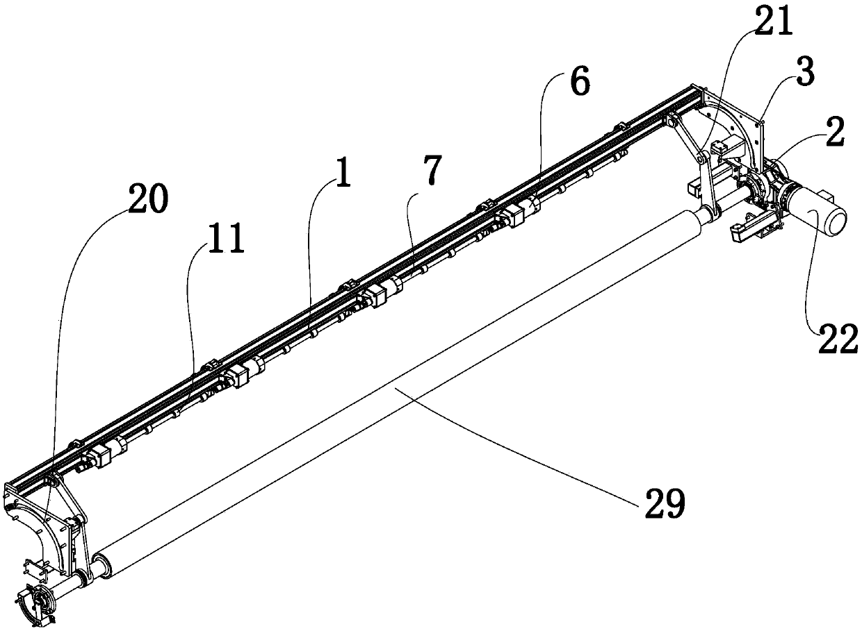
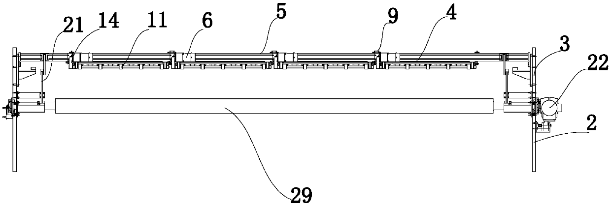
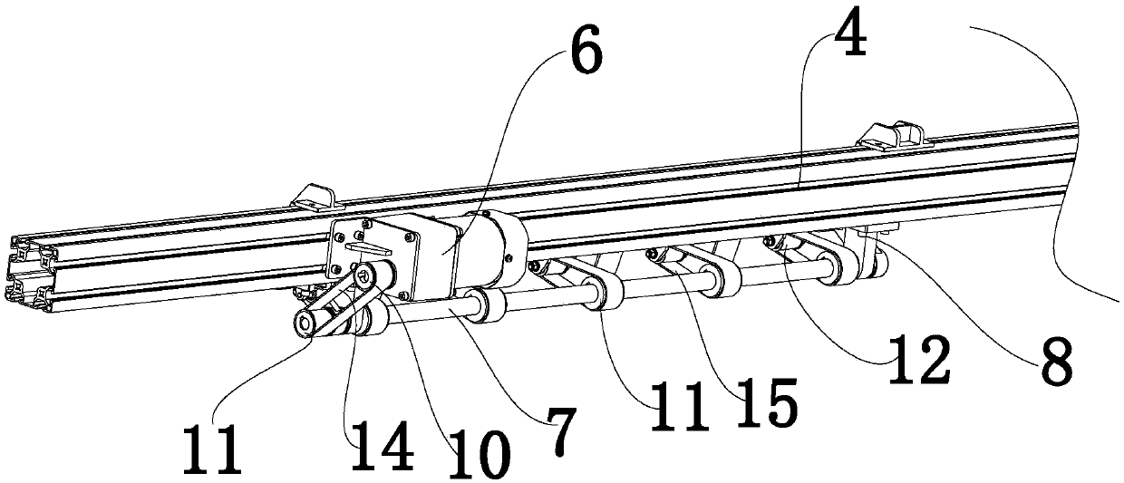
[0037] The present invention will be described in detail below in conjunction with the accompanying drawings. The description in this part is only exemplary and explanatory, and should not have any limiting effect on the protection scope of the present invention. In addition, those skilled in the art can make corresponding combinations of features in the embodiments in this document and in different embodiments according to the descriptions in this document.

[0038] Embodiments of the present invention are as follows, with reference to Figure 1-5, an automatic cloth head winding device, including a winding mechanism 1, a turning mechanism and a mounting seat 2, the winding mechanism 1 includes a first carrier 4 and at least one set of winding elements, the winding elements include a driving element 6, a transmission shaft 7 , a fixed seat 8, a telescopic member 9 and a second bearing member 5, the output shaft of the drive member 6 is provided with a first synchronous wheel ...


PUM


Abstract

The invention relates to an automatic cloth leftover winding device comprising a winding mechanism, a turnover mechanism and a mounting base. The winding mechanism comprises a first bearing part and at least one set of winding parts. The winding parts comprise drive parts, transmission shafts, fixing bases, telescopic parts and second bearing parts; output shafts of the drive parts are provided with first synchronous wheels; the transmission shafts are fixedly sleeved with a plurality of second synchronous wheels; the second bearing parts are provided with driven wheels; at least one second synchronous wheel and the corresponding first synchronous wheel are connected through a first synchronous belt; the other second synchronous wheels are connected with the driven wheels through a secondsynchronous belt; swing arms are arranged at the two ends of the second bearing parts; the transmission shafts and the swing arms are hinged; the movable ends of the telescopic parts are connected with the swing arms or the second bearing parts; and the turnover mechanism is fixed to the mounting base and connected with the winding mechanism. The automatic cloth leftover winding device can achieveautomatic winding of cloth leftovers, manual operation is not needed, safety, high speed and high efficiency are achieved, and cost is saved.

Description

technical field [0001] The invention belongs to the technical field of mechanical equipment, and in particular relates to an automatic cloth head winding device. Background technique [0002] Domestic toilet paper rewinding machines, etc., have a relatively soft paper head, and the paper head can be pasted on the inflatable shaft by blowing air from the nozzle to realize automatic winding, but this method is only suitable for relatively soft materials. For non-woven materials with a certain hardness, the air blowing device cannot wrap it on the inflatable shaft. Therefore, at present, the winding of similar materials is basically done manually. After the traditional non-woven fabric winder is unrolled, the cloth is manually wound on the inflatable shaft. The downtime is long and requires the cooperation of many workers. There are security risks. [0003] The traditional method has the following defects: long downtime, it takes at least 3 minutes from unrolling to manually ...

Claims


Application Information

Patent Timeline
Patent Type & Authority Applications(China)
IPC IPC(8): B65H75/28B65H75/24B65H19/28
CPCB65H75/242B65H19/28B65H75/28
Inventor 朱栗波秦贝贝贺礼谭果胡俊文黄才英
Owner CHANGSHA CTR ROBOTICS
Why Eureka
Try Eureka