
Method and system for measuring pose of industrial mechanical arm

A technology of engineering machinery and mechanical arms, which is applied in the field of measuring the pose and posture of engineering mechanical arms, and can solve the problems of prone to flexible deformation, large precise positioning of terminal operating devices, and long arm frame of multifunctional operating trolleys.

Active Publication Date: 2019-04-12
CHINA RAILWAY CONSTR HEAVY IND
View PDF8 Cites 15 Cited by
  • Summary
  • Abstract
  • Description
  • Claims
  • Application Information

AI Technical Summary

Problems solved by technology

[0003] The multi-function trolley has long arm frame, many joints, heavy weight, and is prone to flexible deformation, and there are dimensional errors in the various parts after processing and assembly. It is very difficult to realize the precise positioning of the terminal operation device. Therefore, a A method that can quickly and accurately obtain the pose of the end of the manipulator

Method used


Image

  • Method and system for measuring pose of industrial mechanical arm
  • Method and system for measuring pose of industrial mechanical arm
  • Method and system for measuring pose of industrial mechanical arm

Examples


Embodiment 1

[0028] First, introduce the following measurement tools used in this example: laser tracker (an example of a coordinate information collector), a foldable target ball mechanism (an example of a target, the specific structure can be as follows Figure 4 shown). The foldable target ball mechanism can be expanded and closed by the drive of the motor, so as to prevent the target ball from being blocked due to the movement of the mechanical arm during the measurement process and ensure the normal progress of the measurement. The structure of the target ball mechanism is not limited here, as long as the target ball can have the above functions.

[0029] Such as Figure 4 As shown, the meaning of each reference sign in the accompanying drawings is as follows: the meaning of each reference sign in the accompanying drawings is as follows: 1, base, 2, foldable target ball, 3, protective plate, 10, target ball support card Seat, 11, protective plate support deck, 12, middle drive frame...

Embodiment 2

[0081] Figure 7 It is the system for measuring the pose and posture of the engineering mechanical arm according to the second embodiment of the present application, and the following reference Figure 7 To illustrate the composition and function of the system.

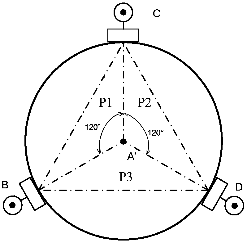
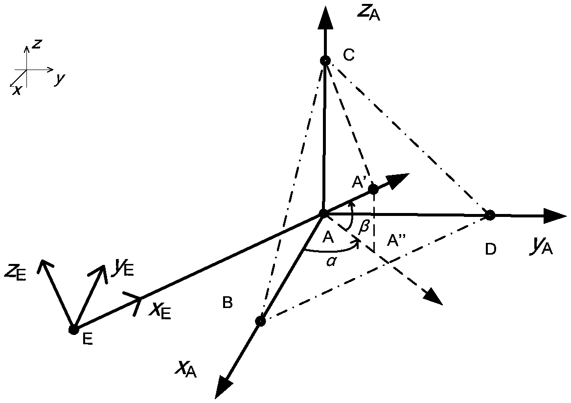
[0082] like Figure 7 As shown, the system includes: at least three targets (illustrated B, C, D), which are installed at the end of the engineering mechanical arm, so that the at least three targets are in the middle of the mechanical arm frame The set point of the axis constitutes a predetermined position relationship; the parameter acquisition device 81, which acquires the position information of the at least three targets in the coordinate system of the robot arm carrier (the position coordinates are mainly measured by a laser tracker) and the The structural dimension parameters and installation dimension parameters of the target; the pose calculation device 82 at the end of the mechanical arm, which uses the pr...


PUM


Abstract

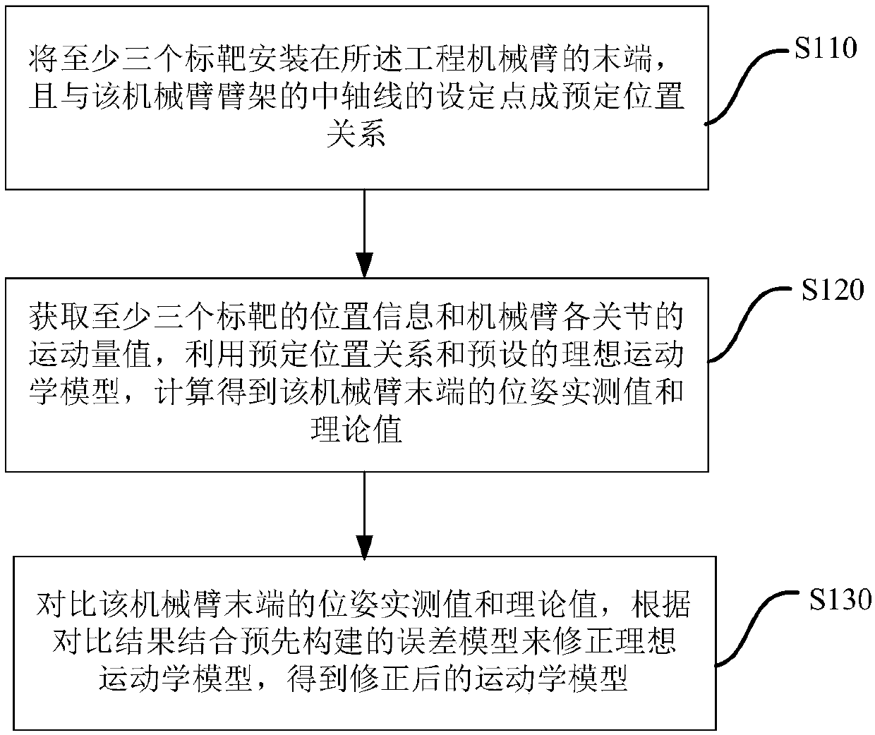
The invention discloses a method and a system for measuring the pose of an industrial mechanical arm. The method comprises the following steps: a target mounting step: mounting at least three targetsat the tail end of the industrial mechanical arm, so that at least three targets and a set point of the axle wire of an arm stand of the mechanical arm form a preset position relationship; a parameteracquiring step: acquiring the position information of the at least three targets on a mechanical arm carrier coordinate system and the structure size parameters and the mounting size parameters of the targets; and a calculation step of the pose of the tail end of the mechanism arm: calculating the pose information comprising position coordinate and posture of the tail end of the mechanical arm onthe mechanical arm carrier coordinate system according to the preset position relationship, the acquired position information and the structure size parameters and the mounting size parameters. Through the adoption of the method, the position and the posture of the mechanical arm can be accurately measured in real time, and operating personnel are assisted to control the movement of the mechanical arm to complete the job task well.

Description

technical field [0001] The invention relates to the field of engineering machinery, in particular to a method and system for measuring the pose of an engineering mechanical arm. Background technique [0002] During the construction of tunnel engineering, in order to prevent the surrounding rock from deforming and breaking, it is usually necessary to reinforce the surrounding rock by erecting arches, installing anchor rods, hanging steel mesh, and spraying concrete. Take the tunnel arch multi-functional operation trolley as an example. This trolley is an automatic tunnel construction equipment integrating arch positioning, installation and welding. The core operating arm is a 10-degree-of-freedom series mechanism. It is the basic requirement of the multifunctional work trolley to realize the predetermined position and attitude of the terminal operation device by the joint pose, and it is also the key technology in its development. [0003] The multi-function trolley has long...

Claims


Application Information

Patent Timeline
IPC IPC(8): B25J9/16B25J19/00
CPCB25J9/1605B25J19/0095
Inventor 刘飞香郑大桥秦念稳王华明李庆李正光
Owner CHINA RAILWAY CONSTR HEAVY IND
Learn More