
Experimental setup for verifying that work done by conservative force is independent of path

An experimental device and a conservative force technology, applied in the field of teaching tools, can solve the problems such as the inability to verify the work of gravity, the inability to accurately judge the precise relationship, and the inability to grasp the work state, and achieve the effects of simple structure, low cost and convenient operation.

Active Publication Date: 2022-03-18
TANGSHAN COLLEGE
View PDF13 Cites 0 Cited by
  • Summary
  • Abstract
  • Description
  • Claims
  • Application Information

AI Technical Summary

Problems solved by technology

[0003] After retrieval, the Chinese patent "Demonstration Device Independent of Gravity Work and Path (ZL2010205345829)" discloses a demonstration device for verifying that gravity work is independent of path. Although the device specifically shows that the gravitational work of objects in different paths is the same, however, It also only shows the conservative force of gravity, and cannot verify the gravitational work of the other two known conservative forces, and the function is relatively simple
In addition, in this device, what is used to display the gravity work is the buffer material filled in the box at the bottom of the channel. It is difficult to accurately see the degree of material depression with the naked eye. Although the general situation of the gravity work can be seen, it cannot be grasped. The accuracy of its accurate work is low, and it is impossible to accurately judge the precise relationship between different paths and gravity work

Method used


Image

  • Experimental setup for verifying that work done by conservative force is independent of path
  • Experimental setup for verifying that work done by conservative force is independent of path
  • Experimental setup for verifying that work done by conservative force is independent of path

Examples


Embodiment 1

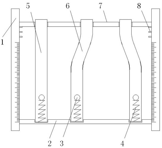
[0035] See attached figure 1 , when it is verified that the gravitational work has nothing to do with the path, the natural length of the spring is one-third of the transparent channel.

[0036] Small balls with the same mass m are released from the top of the smooth transparent channel without initial velocity. Since the transparent channel is smooth and the vertical height of the three glass tubes is h 1 is 100cm, and the height of the vertical part at the bottom of the three glass tubes is h 2 The two heights are indicated by the scale on the bracket on the side of the transparent channel. Since there is no friction between the falling ball and the transparent channel, the free-falling height of the ball is 70cm, that is, h 1 -h 2 , and the three free-falling balls start to accelerate with decreasing acceleration from the moment they contact the spring, and the speed reaches the maximum value V m , the gravity mg of each ball and the spring force F1=kx 1 (x 1 is the ma...

Embodiment 2

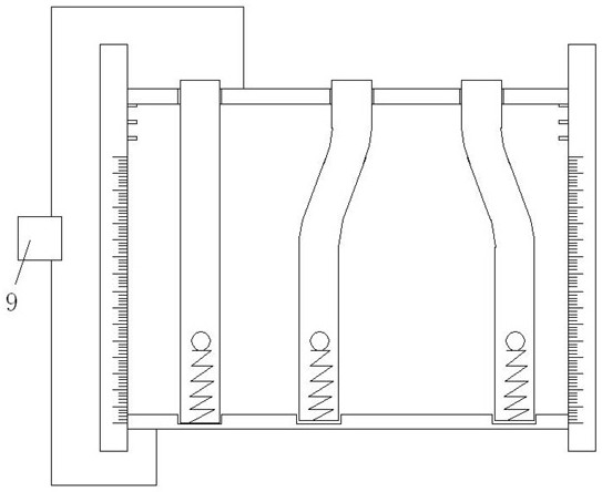
[0038] See attached figure 2 , to verify that the work done by the electric field force has nothing to do with the path. This set of experimental devices also includes a power supply. A uniform electric field is applied to both ends of the transparent channel. The power supply is connected to the metal beam and the bottom plate through wires, and the power supply is connected. U=10v, and the power source is a battery, the electric field strength at both ends of the transparent channel is 100v / m, and the charges of the three light balls with negligible mass are all q. The vertical height of acceleration movement in the channel is still h 1 -h 2 =70cm, after three small balls contact with the spring, do the acceleration movement of acceleration reduction, the electric field strength E=U / d (d is the vertical distance between the two beams and the base plate, and this distance is indicated by the bracket scale), when Eq = kx 1 (x1 is the compression amount of the spring when t...

Embodiment 3

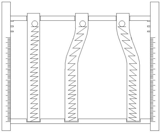
[0041] See attached image 3 , when it is verified that the elastic work has nothing to do with the path, the spring is a light spring, and the natural length of the light spring is the same as the vertical length of the transparent channel.

[0042] Replace the springs in the three transparent channels with light springs with a length of 100 cm, and the springs match the paths of the three transparent straight and curved tubes, and the springs do not contact the side walls of the glass tubes. Release the ball with mass m without initial velocity, the three balls will compress the three springs, and the ball will accelerate with decreasing acceleration from the point of contact with the spring until the maximum speed v m , at this time the gravity mg of each ball and the spring force F=kx 1 Equal (x 1 is the compression amount of the spring when the ball is balanced), after which the spring will continue to be compressed, and the spring force will continue to increase, and t...


PUM


Abstract

An experimental device for verifying that the work done by a conservative force is independent of the path, the base plate is arranged at the lower part between two supports, and the two ends of the base plate are fixedly connected to the opposite inner sides of the two supports respectively; the upper surface of the base plate is provided with at least two inner grooves; The upper parts of the two brackets are respectively provided with corresponding limit blocks; the beam is arranged on the upper part between the two supports, and the beam is a detachable structure, and its two ends are set on the limit blocks; the beam is provided with at least two A through hole; the through hole and the inner groove correspond up and down; a transparent pipe is arranged between the through hole and the inner groove; the transparent pipe includes a straight pipe and a curved pipe; the internal bottom surface of the transparent pipe is provided with a work state display piece, and the small ball and the work The status indicator touches. This kind of experimental device has a simple structure, the verification process is intuitive, accurate, and easy to operate. It can provide direct perceptual knowledge to the market, with low cost and good effect.

Description

technical field [0001] The invention relates to a teaching tool, in particular to an experimental device for verifying that the work of a conservative force is independent of a path during teaching. Background technique [0002] In daily life, the three known conservative forces are gravity, electric field force and elastic force. In the actual physics teaching process, when it is usually verified that the work of the above-mentioned known conservative force has nothing to do with the path, only relevant formulas are used for derivation, and there is no specific experimental device to carry out intuitive and comprehensive verification. [0003] After retrieval, the Chinese patent "Demonstration Device Independent of Gravity Work and Path (ZL2010205345829)" discloses a demonstration device for verifying that gravity work is independent of path. Although the device specifically shows that the gravitational work of objects in different paths is the same, however, It also only ...

Claims


Application Information

Patent Timeline
Patent Type & Authority Patents(China)
IPC IPC(8): G09B23/10
CPCG09B23/10
Inventor 黄洪云刘志勇
Owner TANGSHAN COLLEGE
Learn More