
LED lamp device used as landscape

A technology for LED light device and landscape, which is applied to lighting devices, fixed lighting devices, lighting auxiliary devices, etc., can solve the problem of difficulty in adjusting the illumination angle of landscape LED lights, and achieve the effect of convenient installation.

Inactive Publication Date: 2019-04-09
SHANGLUO UNIV
View PDF7 Cites 8 Cited by
  • Summary
  • Abstract
  • Description
  • Claims
  • Application Information

AI Technical Summary

Problems solved by technology

[0003] However, the landscape LED lights in the prior art are all fixedly installed, which makes it difficult to adjust the irradiation angle of the landscape LED lights.

Method used


Image

  • LED lamp device used as landscape
  • LED lamp device used as landscape
  • LED lamp device used as landscape

Examples


Embodiment 1

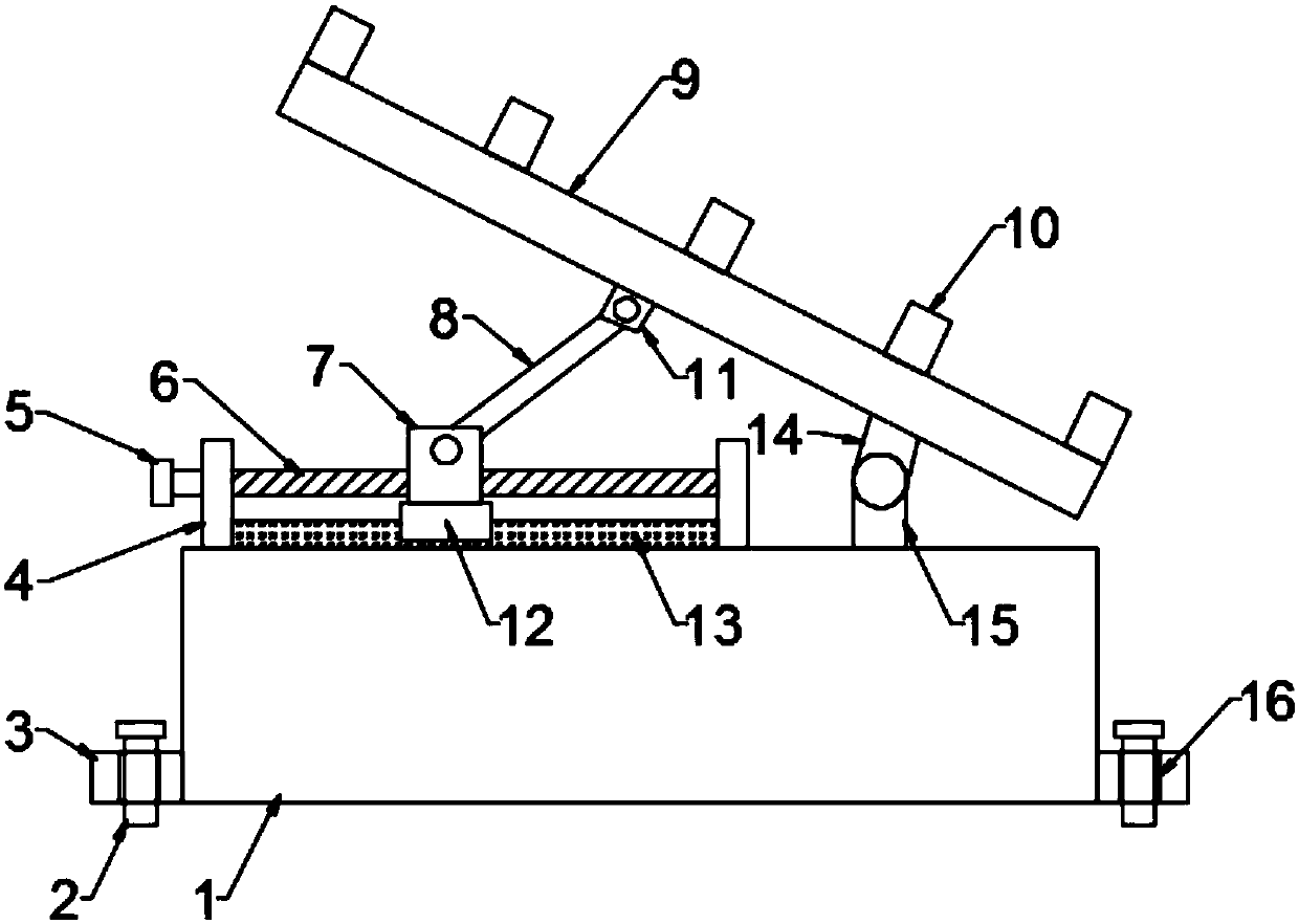
[0024] see Figure 1-2 , in an embodiment of the present invention, a device used as a landscape LED lamp includes a base 1, a lamp holder 9 is provided on the upper side of the base 1, and an LED lamp 10 is installed on the lamp holder 9; The second connection seat 15, the first connection seat 14 is installed on the lower end surface of the lamp holder 9, the first connection seat 14 and the second connection seat 15 are hinged, so that the lamp holder 9 can rotate, and there is a connection between the base 1 and the lamp holder 9 Angle adjustment mechanism, the base 1 is also provided with a sliding mechanism, through the cooperation of the angle adjustment mechanism and the sliding mechanism, the lamp holder 9 can be driven to rotate, the angle of the lamp holder 9 can be adjusted, and the irradiation angle of the LED lamp 10 can be adjusted.

[0025] Described angle adjusting mechanism comprises screw mandrel 6 and threaded block 7, and the upper end surface of base 1 is...

Embodiment 2

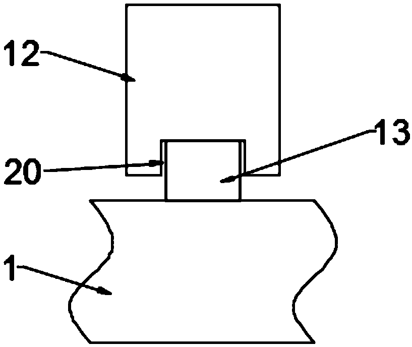
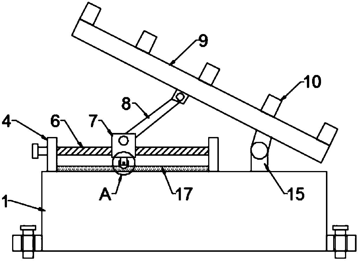
[0032] see Figure 3-5 , in the embodiment of the present invention, a device used as a landscape LED lamp is different from Embodiment 1 in that the sliding mechanism includes a guide rail 17 and a pulley support 19, the guide rail 17 is installed on the upper end surface of the base 1, and the pulley support Seat 19 is installed on the lower end face of threaded block 7, pulley 18 that cooperates with guide rail 17 is installed on the pulley support 19, through the cooperation of fixed side plate 4, turning handle 5 and screw mandrel 6, turning turn handle 5 drives screw mandrel 6 rotates, the threaded block 7 can be driven to move left and right along the screw mandrel 6 through the threaded cooperation of the screw mandrel 6 and the threaded block 7, and the pulley 18 rolls along the guide rail 17, so that the stability of the threaded block 7 when moving is better.

[0033] The working principle of the embodiment of the present invention is: when in use, it can be used as...


PUM


Abstract

The invention relates to the technical field of landscape LED (light-emitting diode) lamp, in particular to an LED lamp device used as a landscape. The LED lamp device comprises a base, wherein a lampholder is arranged on the upper side of the base; LED lamps are mounted on the lamp holder; a second connecting seat is mounted on the upper end face of the base; a first connecting seat is mounted on the lower end face of the lamp holder; the first connecting seat is articulated with the second connecting seat; an angle adjustment mechanism is arranged between the base and the lamp holder; a slide mechanism is also arranged on the base; the angle adjustment mechanism comprises a screw rod and a threaded block; and the screw rod penetrates through the threaded block and is in threaded connection with the threaded block. According to the LED lamp device used as the landscape, a rotating handle is matched with the screw rod; the screw rod can be driven to rotate by rotation of the rotatinghandle; the threaded block can be driven to move left and right along the screw rod through threaded fit between the screw rod and the threaded block and matching of the slide mechanism; the threadedblock, the connecting rod, an articulation bearing, the first connecting seat and the second connecting seat are matched to drive the lamp holder to rotate and adjust an angle of the lamp holder; andthe adjustment of illumination angles of the LED lamps is achieved.

Description

technical field [0001] The invention relates to the technical field of landscape LED lights, in particular to a landscape LED light device. Background technique [0002] LED, light-emitting diode, is a solid-state semiconductor device that can convert electrical energy into visible light, and it can directly convert electricity into light. The heart of LED is the wafer of a semiconductor, and one end of wafer is attached on a bracket, and one end is negative pole, and the other end connects the positive pole of power supply, and whole wafer is encapsulated by epoxy resin. With the rapid development of urban construction, LED lights are used more and more widely. For example, in squares, residential areas, public green spaces and other places, landscape LED lights can be seen everywhere. Through the search of landscape LED lights, the ornamental value of urban buildings can be increased. [0003] However, the landscape LED lights in the prior art are all fixedly installed, w...

Claims


Application Information

Patent Timeline
Patent Type & Authority Applications(China)
IPC IPC(8): F21S8/00F21V21/14F21V21/00F21Y115/10
CPCF21S8/00F21V21/00F21V21/14F21Y2115/10
Inventor 张娜刘坤陈垚袁训锋赵伟杰陈欣
Owner SHANGLUO UNIV
Learn More