
Time-domain tracking method and device under discontinuous reception and user equipment

A discontinuous reception and user equipment technology, applied in the field of time-frequency tracking methods, devices and user equipment, can solve problems such as inability to receive data, time-frequency offset at the UE receiving end, and affecting DRXON receiving performance, so as to reduce power consumption, Effect of Guaranteed Reception Performance

Active Publication Date: 2019-04-05
SPREADTRUM COMM (SHANGHAI) CO LTD
View PDF2 Cites 8 Cited by
  • Summary
  • Abstract
  • Description
  • Claims
  • Application Information

AI Technical Summary

Problems solved by technology

In the current 5G NR system design, 3GPP has not given the design of how to track the reference signal in time and frequency under the DRX transmission state.
If time-frequency tracking is not performed before DRX ON, due to changes in equipment and the environment, it will cause different degrees of time-frequency offset at the UE receiving end, affecting the receiving performance of DRX ON, resulting in the inability to receive data

Method used


Image

  • Time-domain tracking method and device under discontinuous reception and user equipment
  • Time-domain tracking method and device under discontinuous reception and user equipment
  • Time-domain tracking method and device under discontinuous reception and user equipment

Examples


Embodiment 1

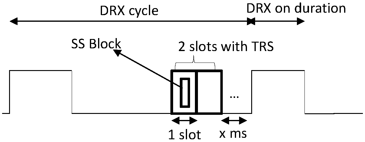
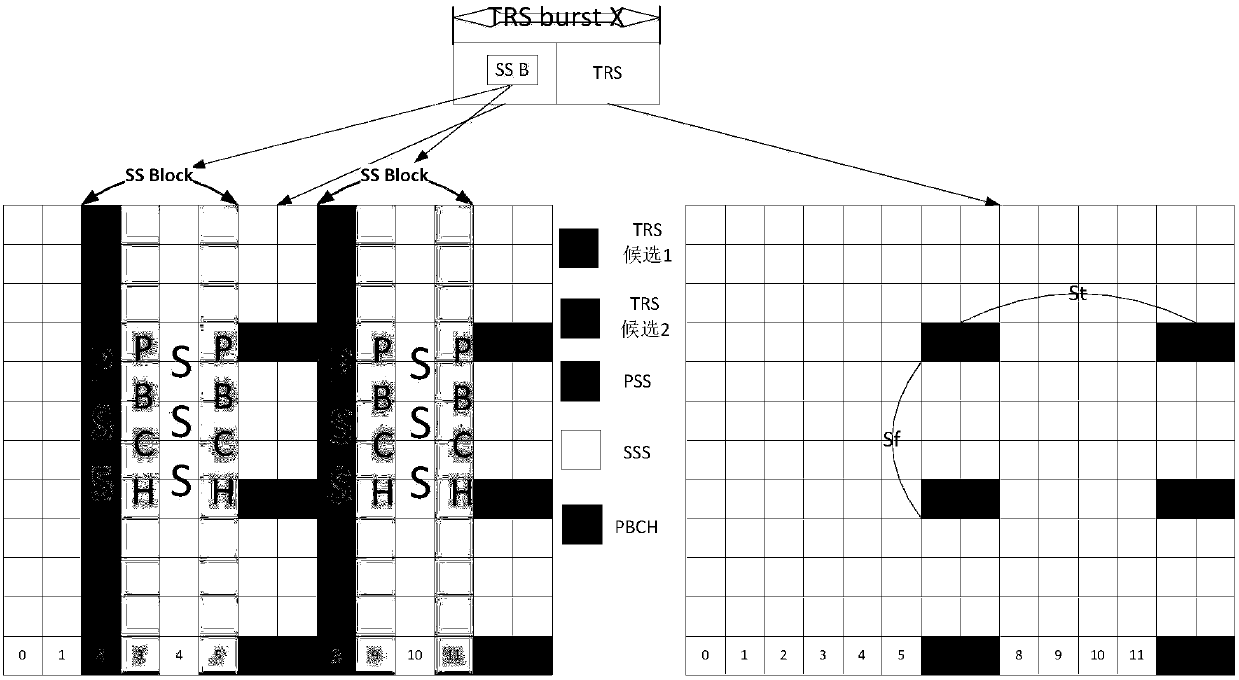
[0057] In the DRX state, TRS adopts 2-slot burst, and 2 SSBs are overlapped on the first slot of TRS, and one of the SSBs and TRS is intended to be on the same site (the base station will send two SSBs at the same time, but for the For the UE, only one SSB to be co-sited with its TRS can be used), such as figure 2 shown. In this scenario, an implementation solution is: the positions of the TRS symbols on the two slots are both 6 / 12 or 7 / 13; one slot duration is reserved before DRX Resource allocation of 1 PRB in the domain image 3 shown.

[0058] Another implementation scheme is: the TRS symbol position on the first slot is 7 / 12, and the TRS symbol position on the second slot is 3 / 8; 0 slot duration is reserved before DRX ON, and the detailed configuration is as follows: 2 in the time domain Slot, resource allocation of 1 PRB in the frequency domain Figure 4 shown.

Embodiment 2

[0060] In the DRX state, TRS adopts 2-slot burst, and 1 SSB burst is overlapped on the first slot and the second slot of TRS respectively, and each SSB burst has 2 SSBs respectively, among which the site is intended to be shared with TRS The SSB is on the first slot, such as Figure 5 shown. The specific implementation plan is: the TRS symbol positions on the two slots are both 6 / 12 or 7 / 13; 1 slot duration is reserved before DRX ON, and the detailed configuration is such as 2 slots in the time domain and 1 PRB resource in the frequency domain Allocation indication Figure 6 shown.

Embodiment 3

[0062] In the DRX state, TRS adopts 2-slot burst, and 1 SSB is overlapped on the first slot of TRS, and it is planned to be co-sited with TRS, such as Figure 7 shown. The specific implementation plan is: the TRS symbol position on the first slot is 10 / 13, and the TRS symbol position on the second slot is 3 / 6; 0 slot duration is reserved before DRX ON, and the detailed configuration is as follows: 2 slots in the time domain, Resource allocation of 1 PRB in the frequency domain Figure 8 shown.


PUM


Abstract

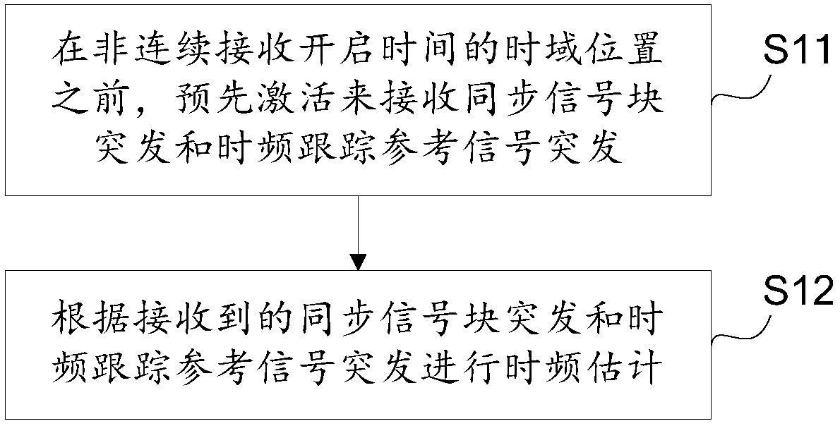
The invention provides a time-domain tracking method and device under discontinuous reception and user equipment. The method comprises that before a time-domain position of a discontinuous reception start moment, bursting of a synchronization signal block and bursting of a time-domain tracking reference signal are received by activation in advance; and the time-domain is estimated according to thereceived bursting of the synchronization signal block and time-domain tracking reference signal. Configuration is carried out according to bursting of different synchronization signal blocks and bursting of the time-domain tracking reference signals, the time domain is estimated before start of discontinuous reception, power consumption of the UE is reduced, and the reception performance of discontinuous reception is ensured.

Description

technical field [0001] The present invention relates to the technical field of wireless communication, in particular to a time-frequency tracking method, device and user equipment under discontinuous reception. Background technique [0002] In the LTE (Long Term Evolution, long-term evolution) system, the base station can periodically send a cell-specific reference signal (Cell-specific Reference Signal, CRS), also known as a common reference signal (Common Reference Signal, CRS), UE (User Equipment , user equipment) keeps synchronized with the base station in time and frequency by tracking this reference signal. In other words, due to hardware differences between the UE and the base station, such as crystal oscillators not being synchronized, there will always be a certain time-frequency deviation. The UE calculates and corrects this time-frequency deviation by tracking the CRS signal periodically sent by the base station. The frequency offset at this time may be called ca...

Claims


Application Information

Patent Timeline
IPC IPC(8): H04W52/02H04W56/00H04J3/06
CPCH04J3/0602H04J3/0638H04W52/0225H04W56/001Y02D30/70
Inventor 贾亚男周化雨汪绍飞黄甦
Owner SPREADTRUM COMM (SHANGHAI) CO LTD
Learn More