Multifunctional intelligent charging device
An intelligent charging and multi-functional technology, applied in the direction of circuit devices, battery circuit devices, current collectors, etc., can solve the problems of inconvenient storage and processing of charging lines, inconvenient storage and processing of small objects, poor charging selectivity, etc., to achieve convenient wireless charging processing, Easy to adjust and handle, to meet the selective effect
- Summary
- Abstract
- Description
- Claims
- Application Information
AI Technical Summary
Problems solved by technology
Method used
Image
Examples
Embodiment 1
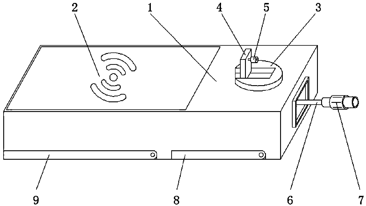
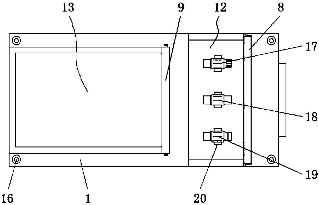
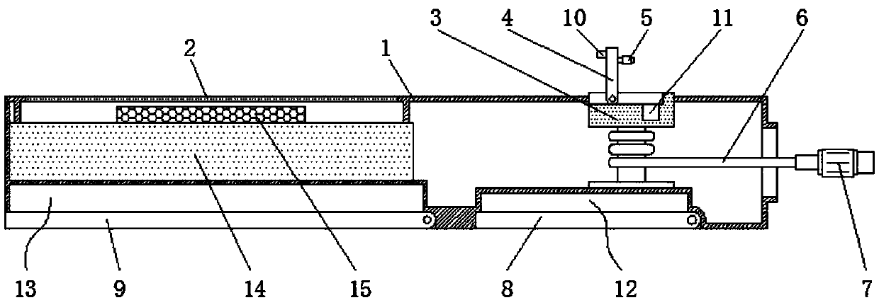
[0026] Embodiment one, with reference to Figure 1-5 , a multi-functional intelligent charging device, including a housing 1 and a battery 14, a glass plate 2 is embedded on one side of the top of the housing 1, and the inside of the housing 1 is located on one side of the glass plate 2 and is rotatably connected with a through-housing The winding frame 3 of 1, the top side of the winding frame 3 is connected with the rotary plate 4 through the rotation of the rotating shaft, and the one side of the rotary plate 4 is connected with the roller 5 through the rotation of the rotating shaft, and the setting of the roller 5 is convenient for the rotation of the rotary plate 4. Rotation adjustment processing, the outside of the winding frame 3 is wound with a charging line 6 that runs through the housing 1, one end of the charging line 6 is provided with a transmission joint 7, one end of the transmission joint 7 is welded with a connecting sleeve 25, and the inside of the connecting...
Embodiment 2
[0027] Embodiment two, refer to figure 2 , 3 And 5, the four corners of the bottom of the housing 1 are embedded with anti-skid pads 16, the setting of the anti-skid pads 16 can improve the stability of the housing 1, and the outer side of the rotary plate 4 is welded with a fixed block 10, fixed The setting of block 10 is convenient for turning plate 4 to rotate and adjust.
Embodiment 3
[0028] Embodiment three, refer to image 3 and 5 , the winding frame 3 is a convex structure in the middle, the top of the winding frame 3 is located below the roller 5 and has a placement groove 11, the setting of the placement groove 11 is used to accommodate the roller 5 on the rotating plate 4, so as to facilitate The retracting of rotating plate 4.
PUM
 Abstract
Description
Claims
Application Information
 - R&D
- Intellectual Property
- Life Sciences
- Materials
- Tech Scout
- Unparalleled Data Quality
- Higher Quality Content
- 60% Fewer Hallucinations
Browse by: Latest US Patents, China's latest patents, Technical Efficacy Thesaurus, Application Domain, Technology Topic, Popular Technical Reports.
© 2025 PatSnap. All rights reserved.Legal|Privacy policy|Modern Slavery Act Transparency Statement|Sitemap|About US| Contact US: help@patsnap.com


