


Quick Research
Generate reliable direction feasibility study reports for your R&D in just a few steps.

Technical Q&A
Discover and master advanced knowledge NOW. Basics, ideas, possibilities, all at once.

Find Solutions
As an expert in R&D theories, this can generate solutions to your technical problems instantly.

Evaluate Feasibility
Analyze your overall solution with one click, know your potential R&D risks in advance.

Monitor Landscape
Get weekly tech updates, stay abreast of the latest tech innovations and key insights.
Thin-layer chromatography expander
A technology of thin-layer chromatography and developing plate, which is applied in the field of thin-layer chromatography developing instrument, can solve the problems of inconvenient addition of developing agent and/or desiccant, mixing of developing agent and desiccant
- Summary
- Abstract
- Description
- Claims
- Application Information
AI Technical Summary
Problems solved by technology
Method used
Image


Examples
Embodiment 1
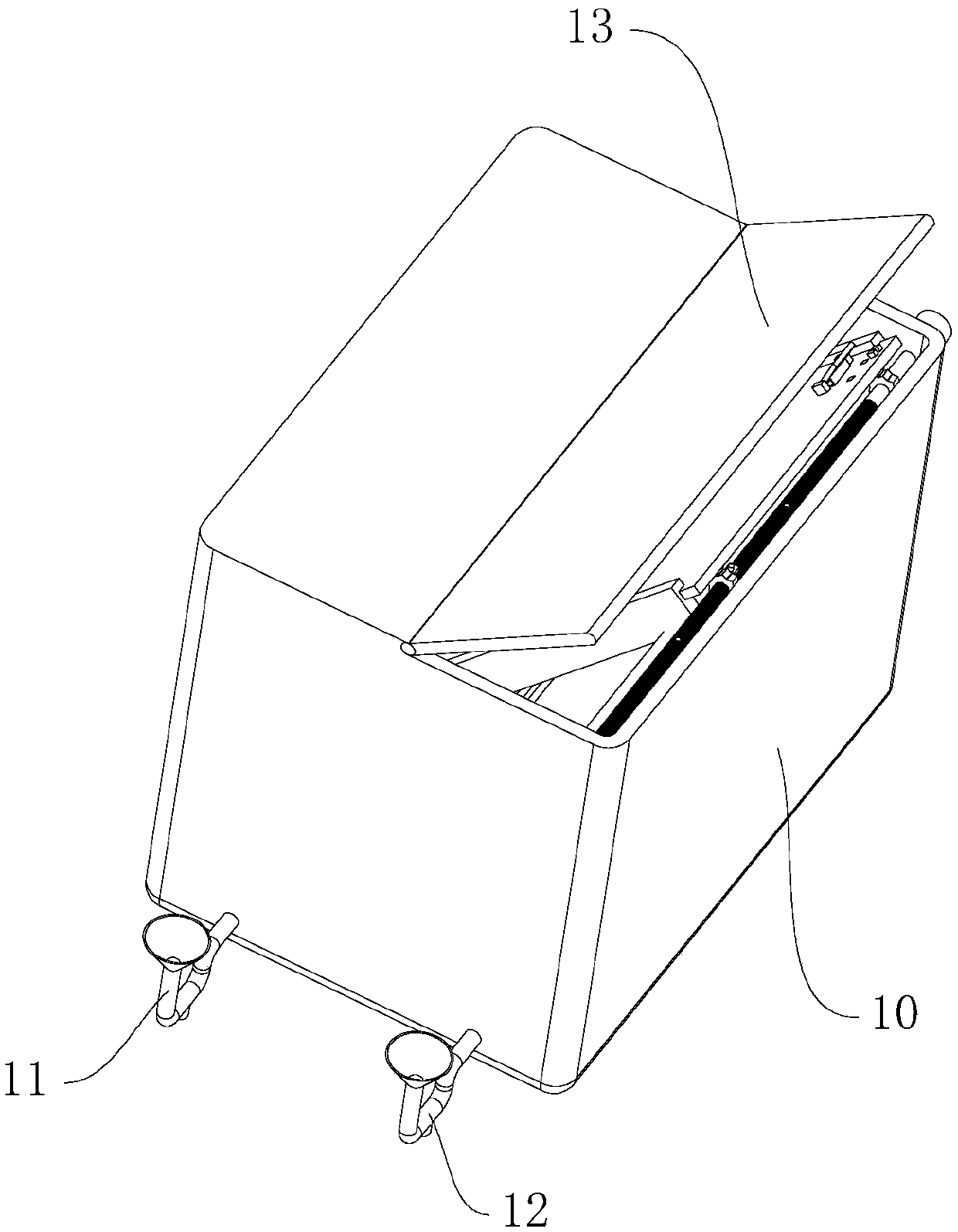
[0044] Such as Figure 1 to Figure 7 As shown, a kind of thin-layer chromatographic developing apparatus provided by the embodiment of the present invention includes a developing box 10 and a developing plate 30, and the developing box 10 is divided into a first developing chamber for storing a developing agent and a first developing chamber for storing a developing agent by a partition tower 17. The second development chamber of the desiccant, the split tower 17 has a conical structure and is located in the middle of the development box 10, such as Figure 1 to Figure 4 The outer side of the development box 10 is provided with a first feeder 11 for adding a developing agent and a second feeder 12 for adding a desiccant, and the first feeder 11 and the second feeder 12 are respectively connected to two development room, such as Figure 7 As shown, the expansion case 10 is provided with a waterproof gas-permeable membrane 50, the waterproof gas-permeable membrane 50 is connect...
Embodiment 2
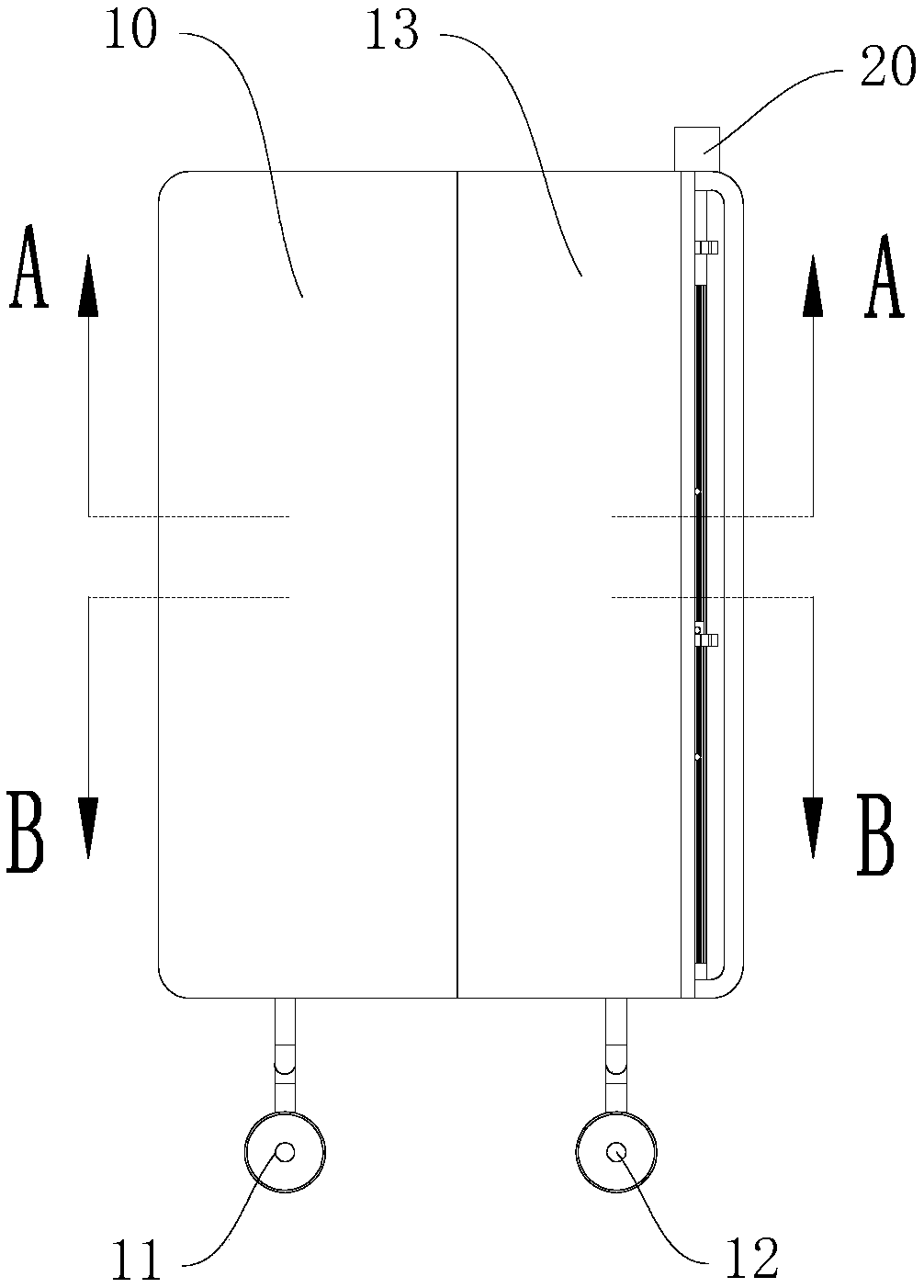
[0048] After the unfolding plate 30 in the prior art is fully unfolded, manual monitoring is required in order to take out the unfolding plate 30 in time, otherwise the developing agent will easily “run” over and cause the experiment to fail. Therefore, this embodiment also includes a plate unloading device, such as Figure 5 to Figure 9 As shown, the unloading device includes a motor 20, a drive shaft 21, a fixed gear 22, an adjustment gear 23, a fixed slide rail 14, an adjustment slide rail 15, and an adjustment shaft 16. 21 is located in the expansion box 10, the output shaft of the motor 20 passes through the side wall of the expansion box 10 and is connected to the drive shaft 21, the fixed gear 22 is coaxially fixed on the drive shaft 21, and the drive shaft 21 is provided with external splines. The adjustment gear 23 is provided with an internal spline that matches the external spline. The adjustment gear 23 is coaxially slidably driven and arranged on the drive shaft 21...
Embodiment 3
[0054] On the basis of Embodiment 2, in order to control the saturation time conveniently, it is convenient to automatically extend the expansion plate 30 into the developing agent after the saturation is completed, such as Figure 15 As shown, this embodiment also includes a control device, which includes a first processor and a timer, the first processor is connected to the timer in signal, and the motor 20 is connected to the first processor in signal. The first processor and the timer are installed on the outer side wall of the expansion box 10 . The saturation time is set by the timer. When the countdown is over, the timer sends a signal to the first processor, and the first processor receives the signal and controls the rotation of the motor 20, which drives the drive shaft 21 and then passes through the fixed gear 22, the adjustment gear 23 and the rack 31. Drive the unfolding plate 30 to extend into the developing agent. The length of its extension can be controlled by...
PUM
 Abstract
Description
Claims
Application Information
 - R&D Engineer
- R&D Manager
- IP Professional
- Industry Leading Data Capabilities
- Powerful AI technology
- Patent DNA Extraction
Browse by: Latest US Patents, China's latest patents, Technical Efficacy Thesaurus, Application Domain, Technology Topic, Popular Technical Reports.
© 2024 PatSnap. All rights reserved.Legal|Privacy policy|Modern Slavery Act Transparency Statement|Sitemap|About US| Contact US: help@patsnap.com