
Manually-controlled shutter valve

A manual control, louver technology, applied in the direction of lift valve, valve details, valve device, etc., can solve the problems of poor stability and sealing, unfavorable working conditions, unreasonable design, etc., and achieve flexible, reliable and stable opening and closing actions. The effect of precision, simple structure

Active Publication Date: 2019-04-05
XI AN JIAOTONG UNIV
View PDF9 Cites 2 Cited by
  • Summary
  • Abstract
  • Description
  • Claims
  • Application Information

AI Technical Summary

Problems solved by technology

However, due to the unreasonable design of the existing manual louver valve, its stability and sealing performance are not strong, which is not conducive to the operator to judge the working condition of the valve, and it is difficult to make timely adjustments. At the same time, there are still problems of wear and corrosion that are difficult to maintain.

Method used


Image

  • Manually-controlled shutter valve
  • Manually-controlled shutter valve
  • Manually-controlled shutter valve

Examples


Embodiment Construction

[0028] The present invention will be further described below in conjunction with accompanying drawing:

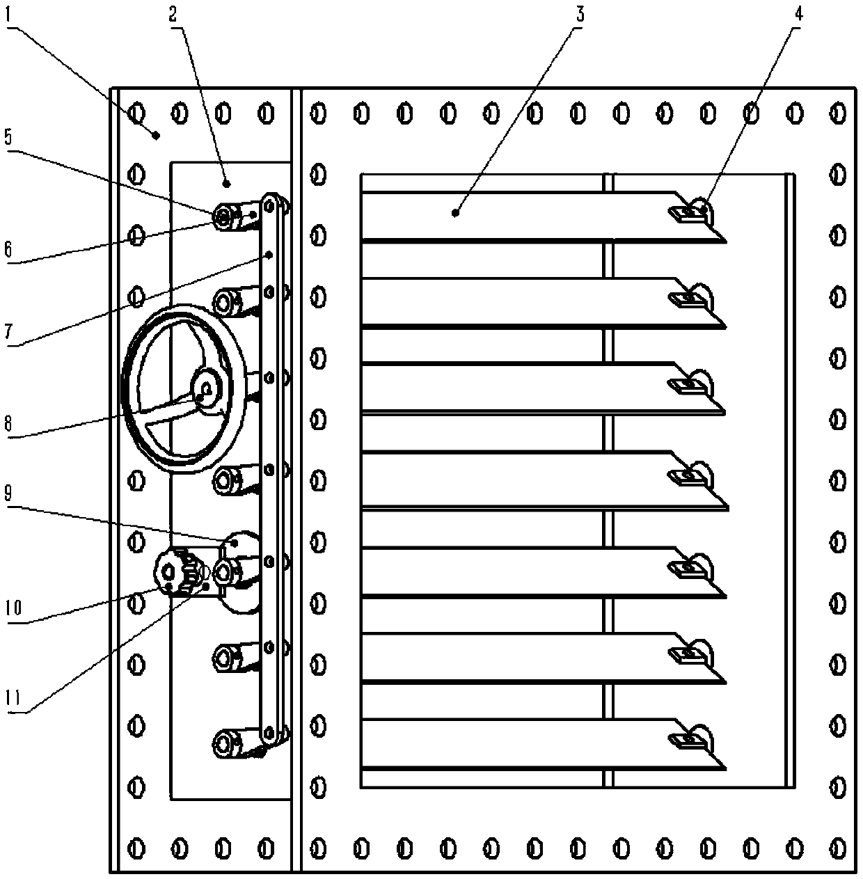
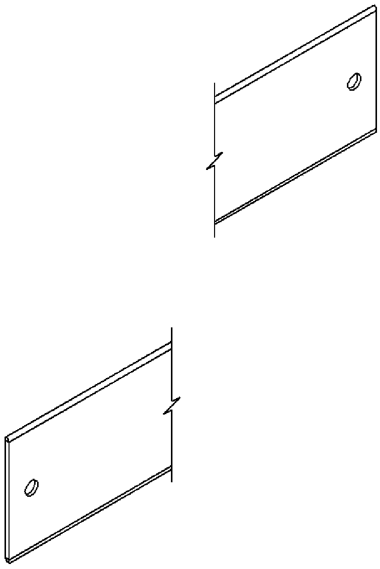
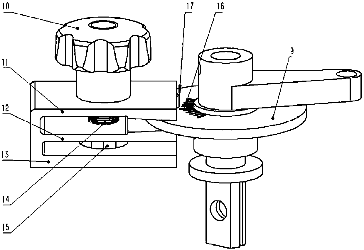
[0029] see Figure 1 to Figure 3 A manually controlled louver valve provided by the present invention includes a flange 1, a valve body 2, a valve plate 3, a right valve shaft 4, a left valve shaft 5, a manual drive mechanism and a control assembly, and the manual drive mechanism includes a crank 6, Connecting rod 7 and large handwheel 8, control assembly comprises wheel disc 9, small handwheel 10, upper clamping plate 11, lower clamping plate 12, base 13, spring 14, threaded rod 15, opening gauge 16 and wedge block 17.

[0030] The flange 1 is connected with the valve body 2; there are several stepped holes symmetrically opened on both sides of the valve body 2, and a sleeve is installed in each stepped hole; the part of the valve shaft located inside the valve body 2 is radially opened with The bolt hole is axially provided with a groove equal to the thickness of the val...


PUM


Abstract

The invention discloses a manually-controlled shutter valve. The valve comprises a flange, a valve body, a valve plate, a valve shaft, the manual driving mechanism and a control assembly, wherein theflange is connected with the valve body, a plurality of stepped holes are symmetrically formed in two side plates of the valve body, and each stepped hole is internally provided with a sleeve, the twoends of the valve plate are both provided with holes, the valve shaft comprises a right valve shaft and a left valve shaft, and the left valve shaft and the right valve shaft are both stepped shafts,the two ends of the plurality of valve plates are respectively connected with the right valve shaft and the left valve shaft, and is arranged on the inner side of the valve body in parallel through the stepped holes in the two side plates of the valve body in the vertical direction, the manual driving mechanism comprises a crank, a connecting rod and a large hand wheel, one end of the crank is fixedly connected with the corresponding left valve shaft, the other end is hinged to the connecting rod, the large hand wheel is connected with any left valve shaft, the left valve shaft can be drivento rotate through the rotation of the large hand wheel, the control assembly is connected with the other left valve shaft and is used for controlling the opening degree of the shutter valve. The valveis simple in structure, easy to operate, high in stability and sealing performance and convenient to maintain in long-term operation.

Description

technical field [0001] The invention belongs to the technical field of valves, in particular to a manually controlled louver valve. Background technique [0002] Shutter valve is a new type of regulating valve, which is mainly used for the regulation and opening and closing control of air, flue gas and other gases in process pipelines, and is widely used in metallurgy, chemical industry and other fields. The shutter valve is mainly composed of valve body, shutter, shaft and control mechanism, and can be used with various actuators for different occasions. [0003] At present, the electrically regulated louver valve uses an electric actuator and a reducer to adjust the opening of the valve. The overall actuator is complex and inconvenient to operate. At the same time, in long-term use, due to wear and corrosion, the stability of the transmission mechanism will be extremely high. If the ground drops, there will be problems such as unreliable valve sealing. The manual control...

Claims


Application Information

Patent Timeline
IPC IPC(8): F16K1/226F16K1/36F16K31/60F16K31/52F16K37/00
CPCF16K1/2261F16K1/36F16K31/52F16K31/60F16K37/0016
Inventor 张荻朱发挥谢永慧陈悦
Owner XI AN JIAOTONG UNIV
Learn More