
Antenna structure and wireless communication device having same

An antenna structure and inner radiator technology, applied in the antenna grounding device, the device that enables the antenna to work in different bands at the same time, the antenna support/installation device, etc., can solve the problems of difficult broadband design, poor radiation performance of the built-in antenna, Easy to interfere and other issues

Active Publication Date: 2019-04-02
SHENZHEN FUTAIHONG PRECISION IND CO LTD +1
View PDF8 Cites 14 Cited by
  • Summary
  • Abstract
  • Description
  • Claims
  • Application Information

AI Technical Summary

Problems solved by technology

However, the metal shell is easy to interfere with the frequency radiated by the antenna installed in it, and it is not easy to achieve broadband design, resulting in poor radiation performance of the built-in antenna

Method used


Image

  • Antenna structure and wireless communication device having same
  • Antenna structure and wireless communication device having same
  • Antenna structure and wireless communication device having same

Examples


Embodiment Construction

[0020] The following will clearly and completely describe the technical solutions in the embodiments of the present invention with reference to the accompanying drawings in the embodiments of the present invention. Obviously, the described embodiments are only some, not all, embodiments of the present invention. Based on the embodiments of the present invention, all other embodiments obtained by persons of ordinary skill in the art without making creative efforts belong to the protection scope of the present invention.

[0021] It should be noted that when an element is referred to as being "electrically connected" to another element, it may be directly on the other element or there may be an intervening element. When an element is considered to be "electrically connected" to another element, it may be connected by contact, eg, by a wire connection, or non-contact, eg, by a non-contact coupling.

[0022] Unless otherwise defined, all technical and scientific terms used herein ...


PUM


Abstract

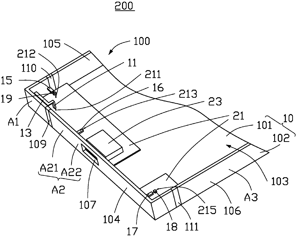
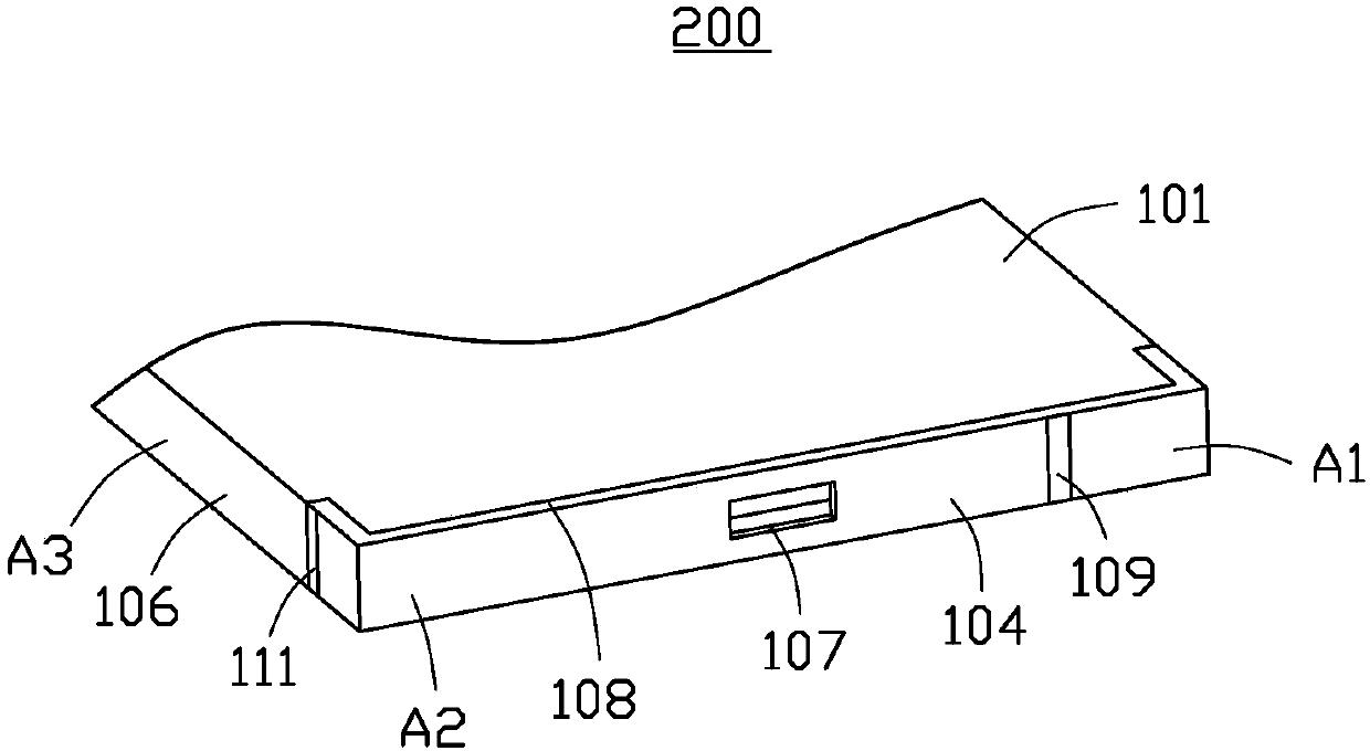
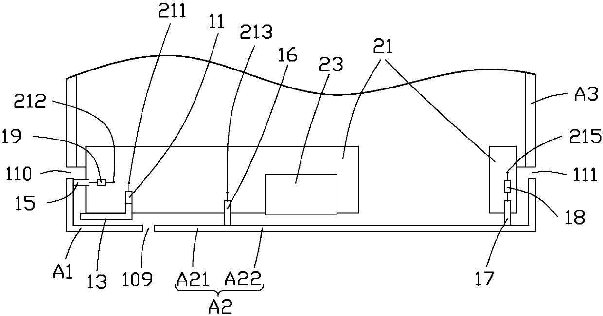
The present invention provides an antenna structure. The antenna structure includes a metal housing, a first feeding portion, a first grounding portion and an inner radiator. The metal housing is provided with a coupling portion and a coupling section, the first feeding portion, the first grounding portion and the inner radiator are all arranged in the metal housing, when a current is fed in froma first feeding point, the current flows through the first feeding portion and the inner radiator, and is coupled to one of the coupling portion and the coupling section through the inner radiator, when the current is subjected to secondary coupling by one of the coupling portion and the coupling section to the other one of the coupling portion and the coupling section to commonly excite three different modes to generate three different radiation frequency bands. The antenna structure can effectively control low, middle and high frequencies of the radiation frequency bands and can meet the demands of Carrier Aggregation (CA). The present invention further provides a wireless communication device having the antenna structure.

Description

technical field [0001] The invention relates to an antenna structure and a wireless communication device with the antenna structure. Background technique [0002] With the advancement of wireless communication technology, wireless communication devices are constantly developing towards a thinner and lighter trend, and consumers have higher and higher requirements for product appearance. Due to the advantages of metal shells in terms of appearance, structural strength, and heat dissipation effects, more and more manufacturers design wireless communication devices with metal shells, such as metal backplanes, to meet the needs of consumers. However, the metal shell is likely to interfere with the frequency radiated by the antenna disposed therein, and it is not easy to achieve broadband design, resulting in poor radiation performance of the built-in antenna. Contents of the invention [0003] In view of this, it is necessary to provide an antenna structure and a wireless com...

Claims


Application Information

Patent Timeline
IPC IPC(8): H01Q5/30H01Q9/04H01Q1/24
CPCH01Q5/30H01Q1/24H01Q9/04H01Q1/48H01Q9/42H01Q21/30H01Q5/328H01Q5/364H01Q5/378H01Q1/243H01Q7/00
Inventor 谢维恩李建桦赫弋翔
Owner SHENZHEN FUTAIHONG PRECISION IND CO LTD
Learn More