A mechanical automatic structure demonstration teaching device

A technology of automatic structure and teaching device, applied in the field of teaching tools, can solve problems such as students being difficult to understand and teachers being laborious in explaining, etc., to achieve the effect of intuitive display, novel design and convenient learning.

Active Publication Date: 2021-01-05
嘉兴市燕知网络科技有限公司
View PDF17 Cites 0 Cited by
  • Summary
  • Abstract
  • Description
  • Claims
  • Application Information

AI Technical Summary

Problems solved by technology

[0005] Regarding how the content of the mechanical transmission part can be controlled by automation, it is not easy for students to understand the combined content of this part, and it is also difficult for the teacher to explain it. If there are specific equipment for demonstration, students will understand it more easily

Method used


Image

  • A mechanical automatic structure demonstration teaching device
  • A mechanical automatic structure demonstration teaching device
  • A mechanical automatic structure demonstration teaching device

Examples


Embodiment 1

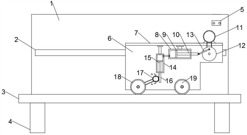
[0027] In the embodiment of the present invention, a mechanical automatic structure demonstration teaching device includes a base plate 3, a vertical plate 1 fixed on the base plate 3 and perpendicular to the base plate 3, and a sliding plate 6; the lower end of the base plate 3 is symmetrically equipped with legs 4 , the legs 4 play a supporting role, the rear end of the sliding plate 6 is fixed with a slider, and the slider is slidably connected with the slide rail 2 arranged at the front end of the vertical plate 1, so that the sliding plate 6 can be horizontally positioned relative to the vertical plate 1 direction, the upper end of the sliding plate 6 is fixed with a receiving plate 7 for installing the motor 11, the receiving plate 7 is placed horizontally and perpendicular to the sliding plate 6, and the lower end of the sliding plate 6 is provided with a pneumatic mechanism driven by the motor 11. The mechanism communicates with the sealing cylinder 14 through a communi...

Embodiment 2

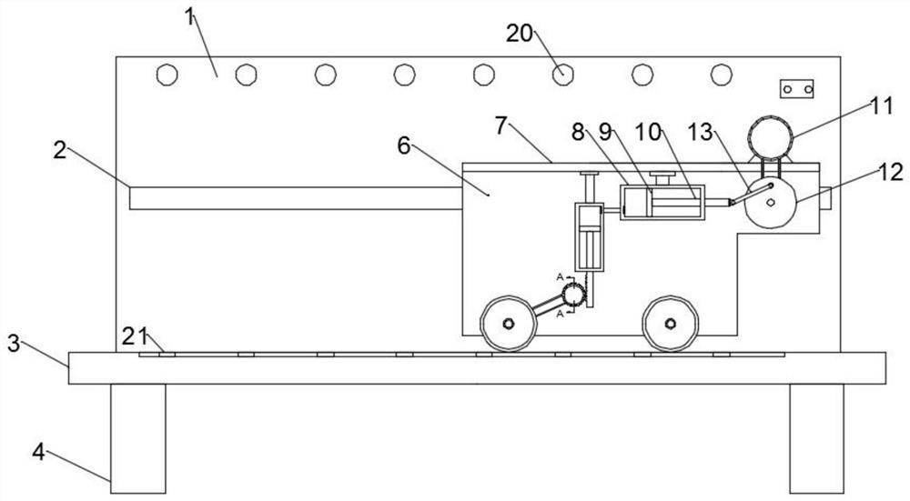
[0034] In the embodiment of the present invention, a mechanical automatic structure demonstration teaching device includes a base plate 3, a vertical plate 1 fixed on the base plate 3 and perpendicular to the base plate 3, and a sliding plate 6; the lower end of the base plate 3 is symmetrically equipped with legs 4 , the legs 4 play a supporting role, the rear end of the sliding plate 6 is fixed with a slider, and the slider is slidably connected with the slide rail 2 arranged at the front end of the vertical plate 1, so that the sliding plate 6 can be horizontally positioned relative to the vertical plate 1 direction, the upper end of the sliding plate 6 is fixed with a receiving plate 7 for installing the motor 11, the receiving plate 7 is placed horizontally and perpendicular to the sliding plate 6, and the lower end of the sliding plate 6 is provided with a pneumatic mechanism driven by the motor 11. The mechanism communicates with the sealing cylinder 14 through a communi...


PUM


Abstract

The invention relates to a teaching aid, and in particular to a mechanical automatic structure demonstration teaching device. The device comprises a base plate as well as a vertical plate and a sliding plate which are fixed to the base plate and are perpendicular to the base plate, wherein a sliding block is fixed to the back end of the sliding plate; a pneumatic mechanism, which is driven by a motor, is arranged at the lower end of the sliding plate; the pneumatic mechanism communicates with a sealing cylinder by virtue of a communicating pipe; a pneumatic rod, which runs through the lower end of the sealing cylinder and is fixedly connected to a gear plate, is arranged in the sealing cylinder; a gear, which is meshed with the gear plate, is arranged at the side end of the gear plate; thegear is rotatably arranged on the sliding plate by virtue of a rotating shaft; a columnar cylinder, which sleeves the outer side of the rotating shaft, is also rotatably arranged on the sliding plate; the columnar cylinder is connected to the rotating shaft by virtue of a ratchet mechanism; and the outer side of the columnar cylinder is rotatably connected to a driving wheel by virtue of a transmission belt. The teaching device provided by the invention, by driving the sliding plate to do linear motion through the pneumatic mechanism and the ratchet mechanism, can achieve intuitive display ofa mechanical automatic structure, so as to facilitate study.

Description

technical field [0001] The invention relates to a teaching tool, in particular to a mechanical automatic structure demonstration teaching device. Background technique [0002] Mechanical automation: Automation refers to the process in which a machine or device is automatically operated or controlled according to a predetermined program or instruction without human intervention, and mechanical automation is the process in which a machine or device is automatically controlled by mechanical means. [0003] The time when mechanical automation really shined was during the industrial revolution in the modern West. At that time, Watt’s improved steam engine used multiple mechanical automatic control and adjustment systems: centrifugal governors and throttle valves. Centrifugal governor created a new milestone in mechanical automatic control. [0004] The realization of mechanical automation has led mechanical production to a new field. Through the automatic control system, it has ...

Claims


Application Information

Patent Timeline
Patent Type & Authority Patents(China)
IPC IPC(8): G09B25/02
CPCG09B25/02
Inventor 徐宗刚史丰荣袁凤林莉莉孙岩志
Owner 嘉兴市燕知网络科技有限公司
Why Eureka
Try Eureka