
A thermal fusion effect pile end stiffness adjustment device

An adjustment device and hot-melt technology, applied in construction, infrastructure engineering and other directions, can solve the problems of short circuit, support stiffness cannot be actively intervened and adjusted according to needs, etc., to achieve simple process steps, flexible and convenient control and adjustment, and easy to achieve. Effect

Active Publication Date: 2019-10-08
NANJING TECH UNIV
View PDF5 Cites 0 Cited by
  • Summary
  • Abstract
  • Description
  • Claims
  • Application Information

AI Technical Summary

Problems solved by technology

[0005] In view of the deficiencies in the prior art, the purpose of the present invention is to provide a thermal fusion effect pile tip stiffness adjustment device, which is stable in operation, safe and reliable, and can further improve the existing pile tip stiffness adjustment device by effectively utilizing the thermal fusion effect. In order to overcome the shortcomings of the existing pile end stiffness adjustment device, the support stiffness cannot be actively intervened and adjusted according to needs, and the pile foundation support stiffness can be intervened and adjusted as needed during the entire process of building construction and use, and the control and adjustment are more efficient. It is flexible and convenient, more reliable in implementation, easy in construction operation, high in adjustment accuracy and high in quantification, and has a significant effect on promoting the development and application of active control theory in the whole process of piled raft foundation. High temperature, insulation, anti-aging performance, and most importantly, it can prevent the short circuit of the device during the working process

Method used


Image

  • A thermal fusion effect pile end stiffness adjustment device
  • A thermal fusion effect pile end stiffness adjustment device
  • A thermal fusion effect pile end stiffness adjustment device

Examples


Embodiment 1

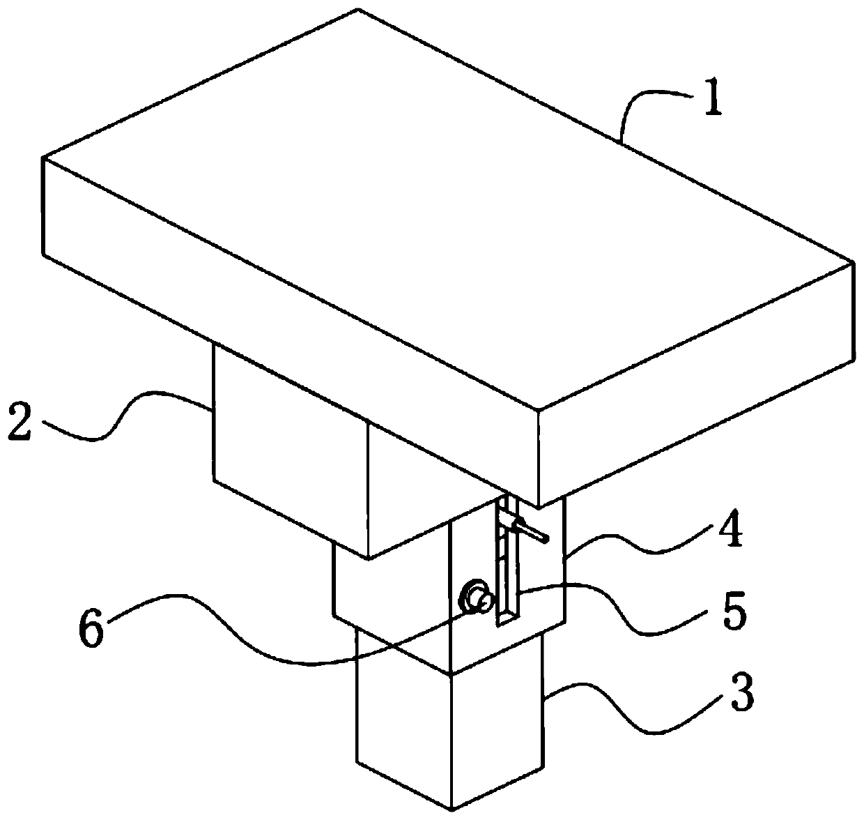
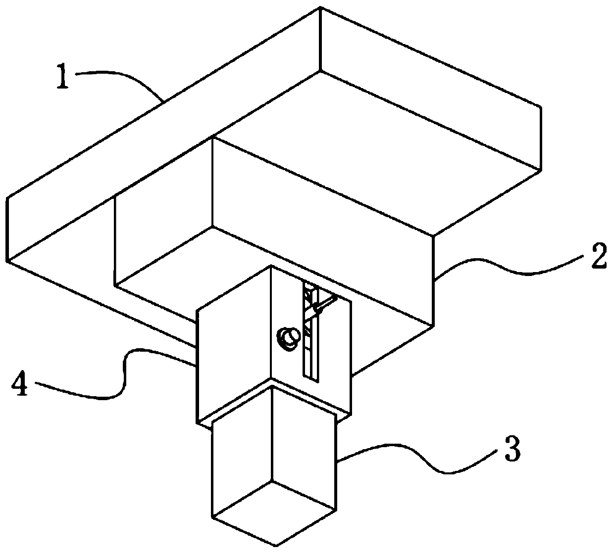
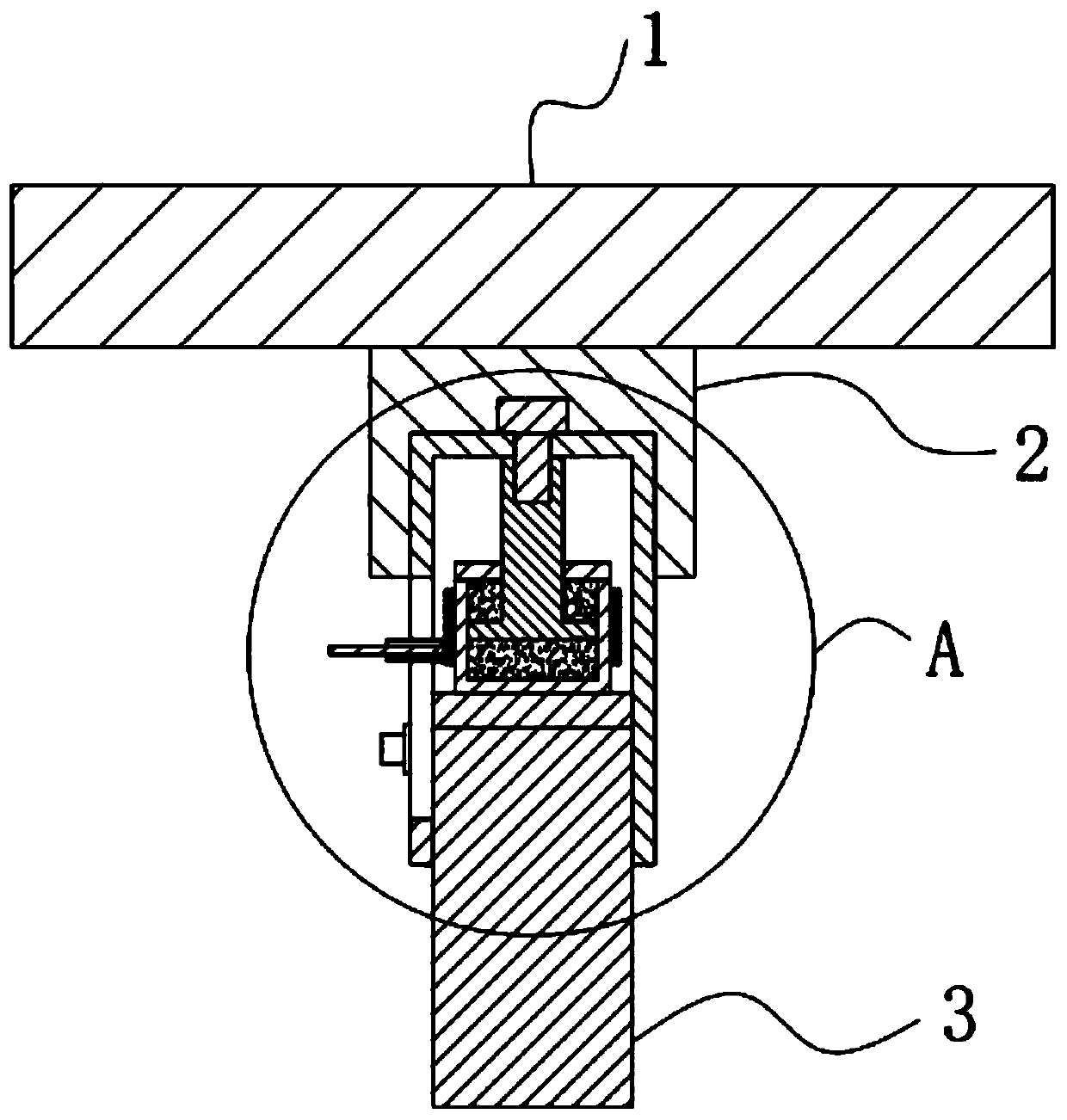
[0047] A thermal fusion effect pile end stiffness adjustment device, such as figure 1 , 2 , 5 and 6, including a raft 1 and a pile body 3 fixedly installed on the pile foundation, the bottom of the raft 1 is poured with a ground beam 2, and the bottom of the ground beam 2 is reserved with an installation groove 12, The inside of the mounting groove 12 is fixed with a cylinder 4, the top of the cylinder 4 is a closed structure, and the bottom of the cylinder 4 is an open structure, and the upper end of the pile 3 is movably inserted in the cylinder. Inside the bottom of the body 4, and the upper end of the pile body 3 is fixedly installed with a top plate 11, and a heat-melt telescopic element 10 is arranged between the top of the top plate 11 and the inner top wall of the cylinder body 4.

[0048] The hot-melt telescopic element 10 effectively uses the hot-melt effect to change its telescopic height to further improve the existing pile end stiffness adjustment device, so as t...

Embodiment 2

[0065] The difference from Example 1 is that a protective layer is also provided on the surface of the electromagnetic heating coil 20, and the protective layer is prepared by the following method:

[0066] Take the following raw materials and weigh them by weight: 20 parts of ceramic particles, 8 parts of alumina powder, 12 parts of silicon nitride, 18 parts of polyethylene, 10 parts of vinyl acetate, 11 parts of acrylic emulsion, 10 parts of phenolic resin, ten parts of alcohol ester 2 parts of diethylthiourea, 2 parts of diethylthiourea, 1 part of high-carbon alcohol fatty acid ester compound, 3 parts of polydimethylsiloxane, 1 part of organic bentonite and 30 parts of ethanol;

[0067] S1. Add the weighed acrylic emulsion, alcohol ester dodeca, diethylthiourea, higher alcohol fatty acid ester complex, polydimethylsiloxane and ethanol into the mixer and stir for 25min at a stirring speed of 500r / min, make mixed solution;

[0068] S2. Add organic bentonite, ceramic particl...

Embodiment 3

[0074] The difference with embodiment 2 is the preparation of protective layer, and its specific preparation method is as follows:

[0075] Take the following raw materials and weigh them by weight: 25 parts of ceramic particles, 10 parts of alumina powder, 14 parts of silicon nitride, 23 parts of polyethylene, 11 parts of vinyl acetate, 13 parts of acrylic emulsion, 11 parts of phenolic resin, ten parts of alcohol ester 3 parts of diethylthiourea, 3 parts of diethylthiourea, 2 parts of high-carbon alcohol fatty acid ester complex, 4 parts of polydimethylsiloxane, 2 parts of organic bentonite and 40 parts of ethanol;

[0076] S1. Add the weighed acrylic emulsion, alcohol ester dodeca, diethylthiourea, higher alcohol fatty acid ester complex, polydimethylsiloxane and ethanol into the mixer and stir for 30min at a stirring speed of 600r / min, make mixed solution;

[0077] S2. Add organic bentonite, ceramic particles, calcium carbonate powder, silicon nitride, polyethylene, viny...


PUM


Abstract

The invention discloses a thermal fusion effect pile end rigidity adjustment device, which comprises a raft and a pile body fixedly installed on the pile foundation. The bottom of the raft is poured with a ground beam, and the bottom of the ground beam is reserved with an installation groove. A cylinder body is fixedly installed inside the cylinder body, and a hot-melt telescopic element is arranged between the upper part of the top plate and the inner top wall of the cylinder body. The present invention is stable in operation, safe and reliable, and further improves the existing pile end stiffness adjustment device by effectively utilizing the thermal fusion effect to overcome the fact that the supporting stiffness cannot be actively intervened and adjusted according to needs after the existing pile end stiffness adjustment device is installed It can intervene and adjust the supporting stiffness of the pile foundation according to the needs in the whole process of building construction and use, the control and adjustment are more flexible and convenient, the implementation is more reliable, the construction operation is simple, the adjustment accuracy is high, and the degree of quantification is high. The development and application of the active control theory for the whole process of raft foundation has a significant promotion effect.

Description

technical field [0001] The invention relates to the technical field of pile raft foundation construction, in particular to a thermal fusion effect pile end stiffness adjusting device. Background technique [0002] With the rapid development of high-rise buildings, the foundation forms that determine the overall stability and safety of high-rise buildings have become larger and more complex, and higher requirements have been put forward for piled raft foundations as the main foundation form. The piled raft foundation of high-rise buildings plays an important role in project construction, and it accounts for an increasing proportion of the total project cost and total construction period. The safety and effectiveness of high-rise building piled raft foundations in the early design, optimization, later construction, and use become increasingly prominent and attract the attention of all parties. The main objects of early design and optimization of the piled raft foundation of h...

Claims


Application Information

Patent Timeline
Patent Type & Authority Patents(China)
IPC IPC(8): E02D27/12
Inventor 周峰申志福孙天佑周泽坤
Owner NANJING TECH UNIV
Learn More