Flange plate drilling clamp of L-shaped tubular part

A drilling jig and tubular technology, applied in the field of flange drilling jigs, can solve problems such as tool tilt and slippage, parts scrapping, poor tool rigidity, etc., to achieve convenient clamping and disassembly, simple structure, and ensure positional accuracy and the effect of size requirements

Inactive Publication Date: 2019-04-02
JIANGXI CHANGHE AVIATION IND
View PDF8 Cites 0 Cited by
  • Summary
  • Abstract
  • Description
  • Claims
  • Application Information

AI Technical Summary

Problems solved by technology

[0002] The hole of the flange of some L-shaped tubular parts on the helicopter interferes with the shorter end of the part, and the hole can only be drilled from the other end. A special extended drill is required. Since the suspension diameter ratio of the extended drill is > 18, the tool rigidity No, the tool often tilts and slips when drilling, causing the part to be scrapped

Method used


Image

  • Flange plate drilling clamp of L-shaped tubular part
  • Flange plate drilling clamp of L-shaped tubular part

Examples


Embodiment Construction

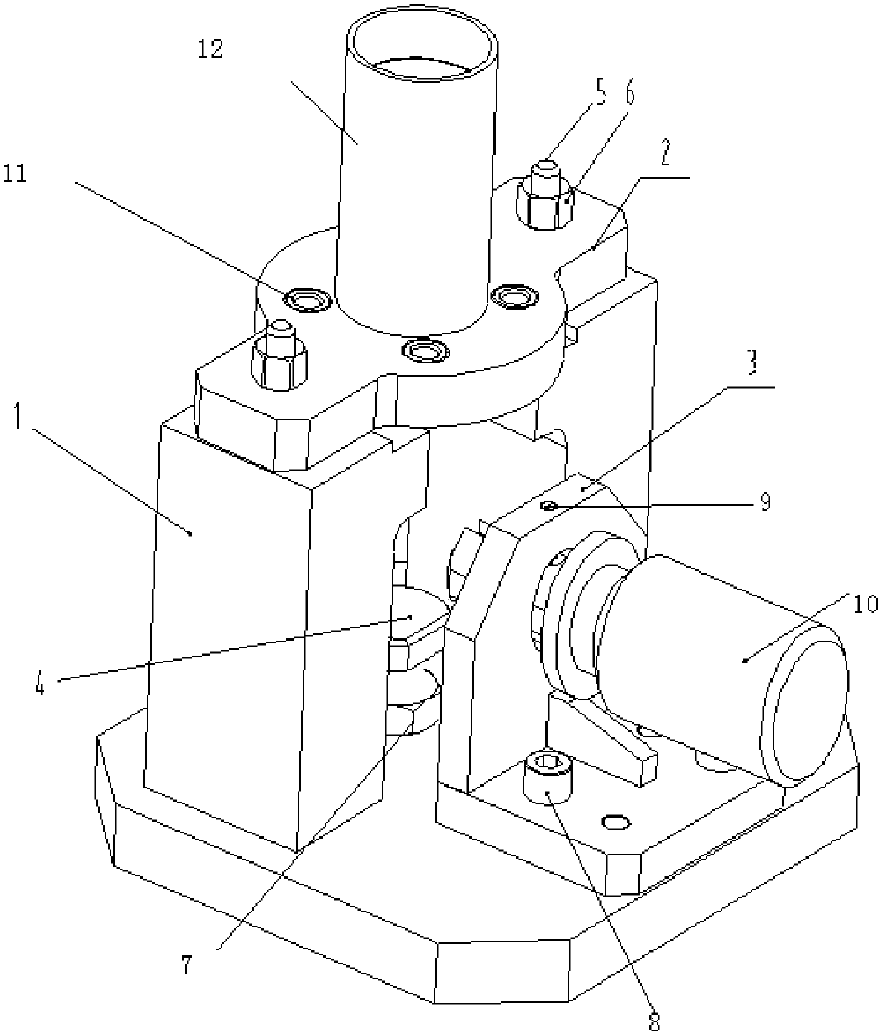
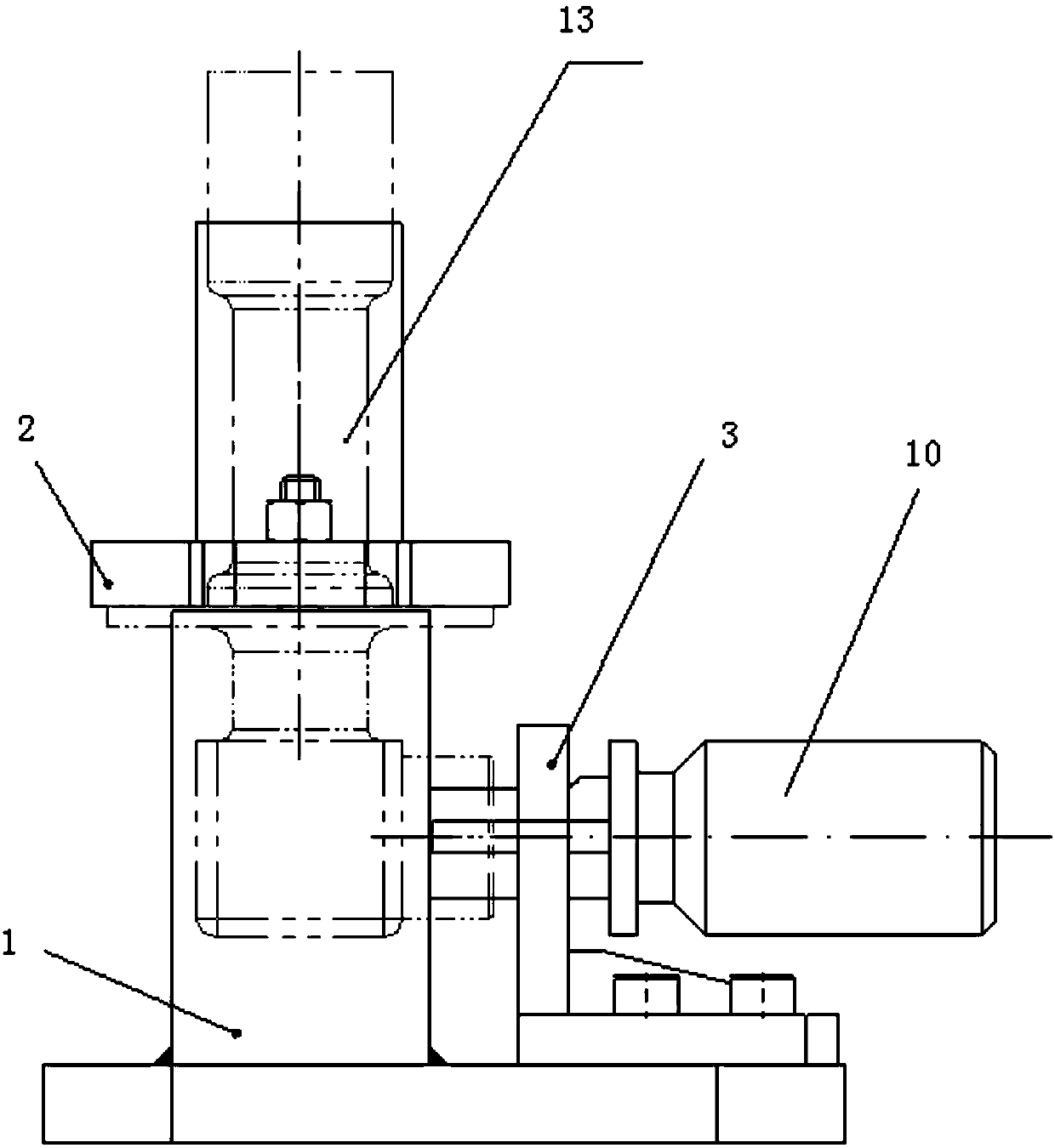
[0013] A flange drilling jig for L-shaped tubular parts, the jig has a pair of uprights 1 and supports 3 on the base, a supporting platform 4 on the base between the uprights 1, and opposite The steps, wherein the flange of the L-shaped tubular part is placed, and a drill template 2 is installed on the upper end surface, and the drill template 2 has a conduit 12 fitted with a gap fit with one end of the L-shaped tubular part; on the support 3, there is A guide pin 10 fitted with the other end of the L-shaped tubular part in clearance fit, the guide pin 10 has a planar part cut along the axial direction and an arc surface part not cut.

[0014] The drill template 2 has a drill bushing 11, and the drill template 2 is installed on the column 1 through stop screws 5 and nuts 6, and positioned by positioning pins. The lower end of the supporting platform 4 has studs, which are installed on the thin nuts 7 of the base. The support 3 is an L-shaped plate structure, and its lower end...


PUM


Abstract

The invention belongs to the technical field of machining, and particularly relates to a flange plate drilling clamp of an L-shaped tubular part. Holes in the flange plate of the L-shaped tubular partinterfere with the shorter end of the part, the special lengthened drill bit needs to be used, and when the drill bit is drilled, the cutter frequently inclines and slides, so that the part is scrapped. According to the flange plate drilling clamp, a pair of stand columns and a support are arranged on the base, a supporting platform is arranged on the base between the stand columns, opposite steps are arranged on the upper end face of the stand columns, the flange plate of the L-shaped tubular part is arranged in the opposite steps, a drilling template is arranged on the upper end surface, and a guide pipe which is in clearance fit with one end of the L-shaped tubular part in a sleeved mode is arranged on the drilling template, and a guide pin which is in clearance fit with the other endof the L-shaped tubular part in a sleeved mode is arranged on the support. The flange plate drilling clamp has the advantages of being accurate in positioning, simple in structure and convenient to clamp and dismount, so that the position precision and the size requirement of to-be-processed holes of the special lengthened drill bit with the suspension diameter ratio larger than 18 can be effectively ensured.

Description

technical field [0001] The invention belongs to the technical field of mechanical processing, and in particular relates to a flange drilling jig for an L-shaped tubular part. Background technique [0002] The hole of the flange of some L-shaped tubular parts on the helicopter interferes with the shorter end of the part, and the hole can only be drilled from the other end. A special extended drill is required. Since the suspension diameter ratio of the extended drill is > 18, the tool rigidity Not good, the tool often tilts and slips when drilling, causing the part to be scrapped. For practical needs, it is necessary to design a special drilling jig to ensure the positional accuracy of the processed holes. Contents of the invention [0003] The object of the present invention is to design a drilling jig that is positioned on the outer circle of the part and adopts other auxiliary supports for orientation and clamping, so as to ensure the position accuracy of the process...

Claims


Application Information

Patent Timeline
Patent Type & Authority Applications(China)
IPC IPC(8): B23B47/28
CPCB23B47/28
Inventor 万磊章梁忠郑乔郑军李晗刘立超范姝芳郭露
Owner JIANGXI CHANGHE AVIATION IND
Why Eureka
Try Eureka