
An RFID reader for fire warehouse

A reader and fire-fighting technology, applied in the field of RFID readers, can solve the problems of difficult disassembly and replacement, difficult use effect, cumbersome and other problems, and achieve the effect of preventing the weakening of magnetic force, excellent use effect and reducing labor intensity.

Pending Publication Date: 2019-03-29
SUZHOU BYCODELABEL INFORMATION TECH CO LTD
View PDF0 Cites 0 Cited by
  • Summary
  • Abstract
  • Description
  • Claims
  • Application Information

AI Technical Summary

Problems solved by technology

[0002] In recent years, with the advancement of micro-integrated circuit technology, RFID readers have been developed, and in the reading process, passive RFID tags do not need batteries, and the energy required for work can be obtained from the magnetic field generated by RFID readers, so its It has also begun to be gradually used in fire-fighting storage to read each fire-fighting equipment and check whether its quality meets the requirements. However, the existing RFID reader for fire-fighting storage has a simple structure and is not easy to use. It is located under the warehouse and the label is also below. It is cumbersome to carry out radio frequency on the stored items, which greatly increases the labor intensity of the staff. At the same time, the handle part of the device is integral. The handle is not easy to disassemble and replace after long-term use, which will affect the hand feeling.

Method used


Image

  • An RFID reader for fire warehouse
  • An RFID reader for fire warehouse
  • An RFID reader for fire warehouse

Examples


Embodiment Construction

[0021] The technical solutions in the embodiments of the present invention will be clearly and completely described below with reference to the accompanying drawings in the embodiments of the present invention. Obviously, the described embodiments are only a part of the embodiments of the present invention, but not all of the embodiments. Based on the embodiments of the present invention, all other embodiments obtained by those of ordinary skill in the art without creative efforts shall fall within the protection scope of the present invention.

[0022] In the description of the present invention, it should be noted that the terms "upper", "lower", "inner", "outer", "front end", "rear end", "two ends", "one end" and "the other end" The orientation or positional relationship indicated by etc. is based on the orientation or positional relationship shown in the accompanying drawings, and is only for the convenience of describing the present invention and simplifying the descriptio...


PUM


Abstract

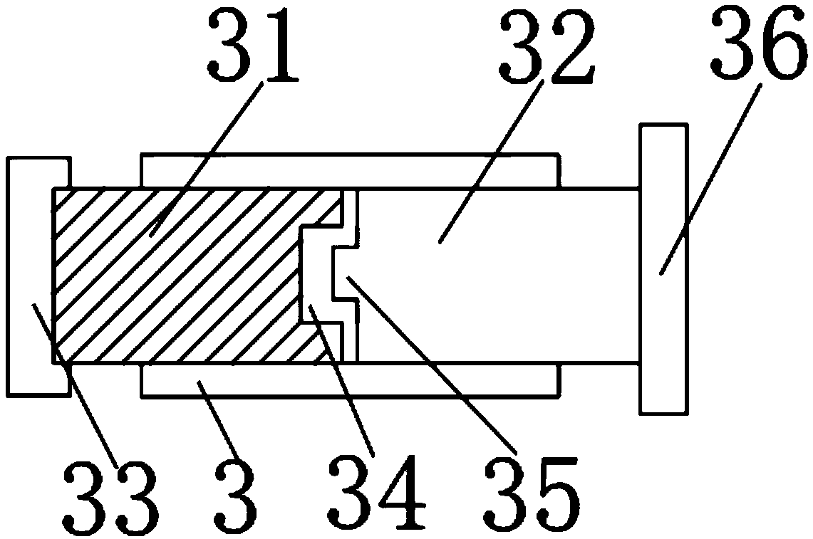
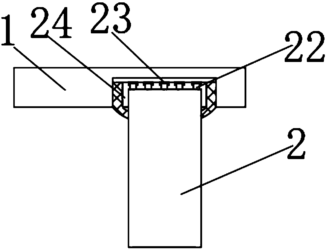
The invention discloses an RFID reader for fire-fighting warehouse, which includes a device body, A switch is arranged on one side of that outer surface of the front end of the device main body, A USBchar interface is arranged on that other side of the out surface of the front end of the device main body, A display screen and a fixing plate are fixedly installed on the outer surface of the upperend of the device main body, and the display screen is positioned on one side of the fixing plate, a button is fixedly installed on the outer surface of the upper end of the fixing plate, a rotating shaft is fixedly installed on one side of the outer surface of the lower end of the device main body, and an RFID reader and writer are wrapped on the outer surface of the rotating shaft. The inventionis provided with a series of structures so that in the use process of the device, the RFID reader can adjust the angle of the RFID reader so as to be adapted to the tags at different positions, the customization is high, the labor intensity of the workers is reduced, the handle required by the device can be customized freely, and the handle is convenient to be disassembled and replaced, the use effect is more excellent, and the use process is optimized. The RFID reader can adjust the angle of the RFID reader and the RFID reader.

Description

technical field [0001] The invention relates to the technical field of an RFID reader, in particular to an RFID reader for fire-fighting storage. Background technique [0002] In recent years, with the advancement of miniature integrated circuit technology, RFID readers have been developed, and during the reading process, passive RFID tags do not require batteries, and the energy required for work can be obtained from the magnetic field generated by the RFID reader. It has also begun to be gradually used in fire-fighting storage to read each fire-fighting appliance and check whether its quality meets the requirements. However, the existing RFID reader for fire-fighting storage has a simple structure and is not easy to use. It is located at the bottom of the warehouse and the label is also below. It is cumbersome to perform radio frequency on the stored items of the device, which greatly increases the labor intensity of the staff. At the same time, the handle part of the devi...

Claims


Application Information

Patent Timeline
IPC IPC(8): G06K7/10
CPCG06K7/10297
Inventor 温志刚
Owner SUZHOU BYCODELABEL INFORMATION TECH CO LTD
Learn More