A low boiling point insulating liquid insulation characteristic test chamber

A technology for testing insulating liquids and characteristics, applied in the direction of testing dielectric strength, measuring electricity, measuring devices, etc., can solve problems such as poor stability, fixed structure, fixed, etc., to avoid changes in physical properties, control human errors, and optimize test devices. Effect

Active Publication Date: 2020-04-03
NORTH CHINA ELECTRIC POWER UNIV (BAODING)
View PDF9 Cites 0 Cited by
  • Summary
  • Abstract
  • Description
  • Claims
  • Application Information

AI Technical Summary

Problems solved by technology

The existing commercial dielectric strength test electrode cups are all based on the IEC-60156 power frequency insulating oil breakdown test standard. Their structures are very fixed and cannot integrate functions such as heating and pressure, let alone realize the boiling state.
The structure of the insulating liquid breakdown, partial discharge test, and flow characteristics test made by the existing research institutions is very fixed, and it is only designed for a single test. If it is adjusted, the entire structure needs to be changed.
At present, there are still experimental schemes based on the design of containers such as beakers, which have been verified to be less stable
[0004] Therefore, the existing testing device for insulating properties of insulating liquid has the defects of inflexible structure and poor stability

Method used


Image

  • A low boiling point insulating liquid insulation characteristic test chamber
  • A low boiling point insulating liquid insulation characteristic test chamber
  • A low boiling point insulating liquid insulation characteristic test chamber

Examples


Embodiment 1

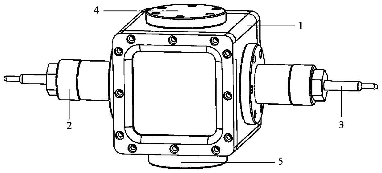
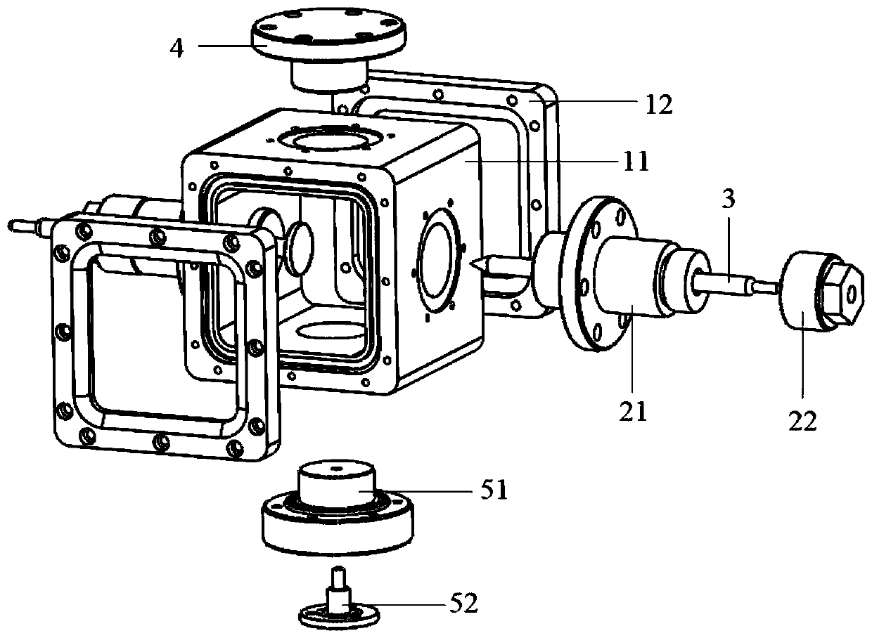
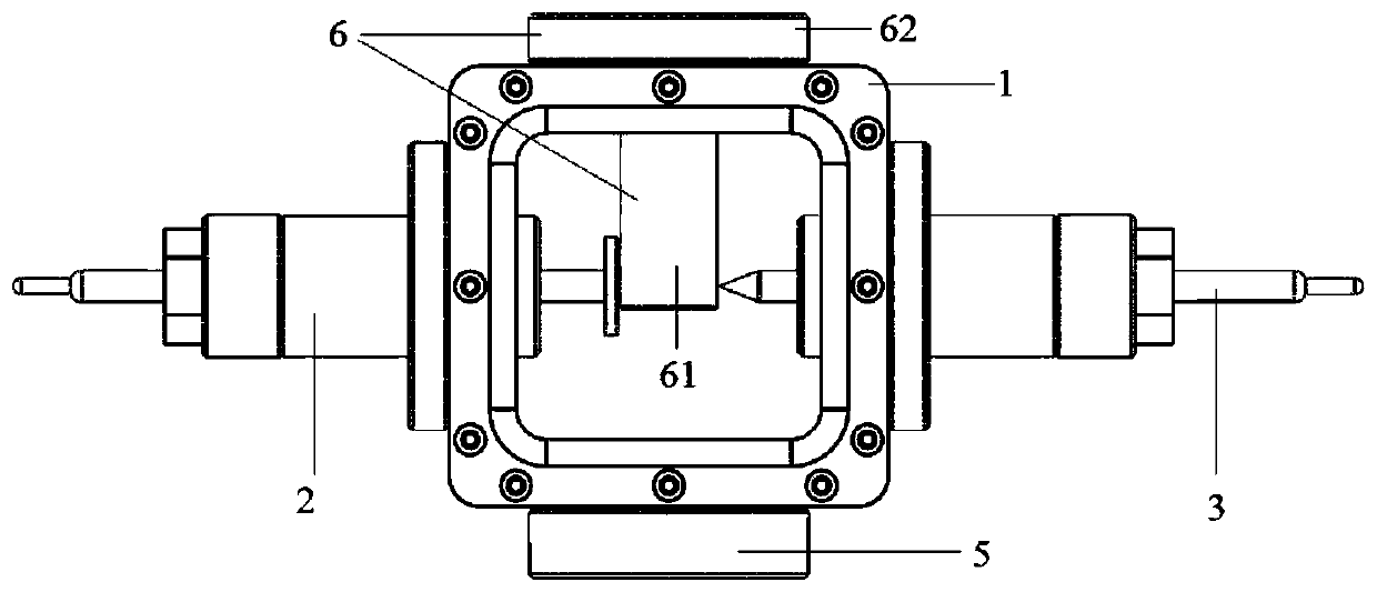
[0040] This embodiment provides a low-boiling point insulating liquid insulation characteristic test chamber, which is specifically a horizontal test structure. In the test, the pole gap is set horizontally, and the direction of bubble flow generated by the heating source is longitudinal, which is set perpendicular to the pole gap; this embodiment The specific structure of the insulation characteristics test chamber for low boiling point insulating liquids is as follows: Figure 1-3 As shown, it includes a cavity 1, an insulating sleeve flange 2, an electrode 3, a blind flange 4 and a transverse heating flange mechanism 5;

[0041] The cavity 1 includes a cavity body 11 and an observation window 12. The cavity body 11 is a hollow rectangular shell structure. The observation window 12 is fixed to the front and rear ends of the cavity body 11 by bolts. The four side walls of the cavity body 11 are respectively One flange mounting hole is provided, and the four flange mounting holes...

Embodiment 2

[0048] This embodiment also provides a low-boiling point insulating liquid insulation characteristic test cavity. The difference between this embodiment and the first embodiment is only that this embodiment provides a longitudinal test cavity in which the pole gap is arranged longitudinally in the test. The bubble flow direction generated by the heating source is also longitudinal, and the bubble flow direction is set parallel to the pole gap;

[0049] Such as Figure 4 , Figure 5 As shown, the technical solution of this embodiment different from the first embodiment is only:

[0050] The insulating sleeve flange 2 is installed at the flange mounting hole on the top of the cavity body 11. There are two blind plate flanges 4, and the two blind plate flanges 4 are respectively installed on the two flanges on both sides of the cavity body 11. In the hole, the longitudinal heating flange mechanism 7 is installed at the flange installation hole at the bottom of the cavity body 11;

[00...


PUM


Abstract

The invention discloses a test cavity for testing low-boiling insulation liquid insulation characteristic, comprising a cavity, an insulating sleeve flange, an electrode, a blind plate flange, a transverse heating flange mechanism and a longitudinal heating flange mechanism. The cavity comprises a cavity body and an observation window fixed to the head end and the tail end of the cavity body. Thecavity body is of an internally hollow shell structure, and a plurality of flange mounting holes are formed in the side wall of the cavity body. The insulating sleeve flange, the blind flange, the transverse heating flange mechanism and the longitudinal heating flange mechanism are arranged in cooperation with the flange mounting holes, so that the test cavity has two structures of lateral test and longitudinal test, and the two test schemes can be flexibly adjusted. One end of the electrode extends into the cavity body, and the other end of the electrode penetrates through the sleeve flange to be locked and fixed through a sealing pressing cap. According to the invention, online adjustment of the electrode can be completed by pumping the electrode rod after the external screwing sealing pressing cap, and even the the test scheme for liquid in the cavity can be changed without removing liquid by rotating, replacing the top flange of the cavity and the like.

Description

Technical field [0001] The invention relates to the technical field of insulation property detection, in particular to a low boiling point insulating liquid insulation property test cavity. Background technique [0002] Phase change cooling technology relies on low-boiling fluorinated liquid products and has been maturely applied to heat dissipation technology. And compared with traditional chlorofluorocarbons, hydrochlorofluorocarbons and even hydrofluorocarbons, the fluorinated fluids developed by 3M and Chemours are more non-flammable, non-toxic, high insulation, low GWP (Global Warming Potential) and low ODP (Ozone Depletion Potential) has become one of the preferred solutions for heat dissipation of power electronic devices and equipment. [0003] However, when applied to high-power power electronic devices and equipment, the insulation problems caused by the high-voltage working conditions are urgently to be assessed. The existing commercial dielectric strength test electro...

Claims


Application Information

Patent Timeline
Patent Type & Authority Patents(China)
IPC IPC(8): G01R31/12
CPCG01R31/1281
Inventor 莫申扬范腾飞赵志斌崔翔
Owner NORTH CHINA ELECTRIC POWER UNIV (BAODING)
Why Eureka
Try Eureka