


Quick Research
Generate reliable direction feasibility study reports for your R&D in just a few steps.

Technical Q&A
Discover and master advanced knowledge NOW. Basics, ideas, possibilities, all at once.

Find Solutions
As an expert in R&D theories, this can generate solutions to your technical problems instantly.

Evaluate Feasibility
Analyze your overall solution with one click, know your potential R&D risks in advance.

Monitor Landscape
Get weekly tech updates, stay abreast of the latest tech innovations and key insights.
Transformer-based electrified water flushing device for radiators
A technology for a flushing device and a radiator, applied in the electric power field, can solve the problems of inability to clean the radiator, inability to clean the radiator, low efficiency, etc., and achieve the effects of simple structure, safe use and high efficiency
- Summary
- Abstract
- Description
- Claims
- Application Information
AI Technical Summary
Problems solved by technology
Method used
Image


Examples
Embodiment 1
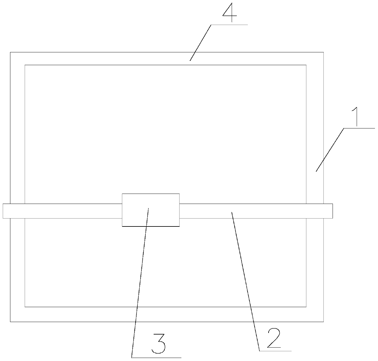
[0033] like Figure 1~2 Shown, the present invention is based on the radiator charged water flushing device of transformer, comprises two vertical rails 1 that are vertically arranged on the radiator, is connected with horizontal horizontal rail 2 between two vertical rails 1, horizontal The track 2 slides up and down along the vertical track 1, the horizontal track 2 is provided with a slider 3, and the slider 3 slides along the straight line where the horizontal track 2 is located;
[0034] A water spray gun is fixedly connected to the slider 3, and the water spray direction of the water spray gun is parallel to the plane where the heat sink on the radiator is located, and the slider 3 is connected with a rod for driving the slider 3;
[0035] When cleaning, the operator on the ground holds the wand to drive the slider 3 to slide left and right along the horizontal track 2, and the horizontal track 2 slides up and down along the vertical track 1, and the water spray gun on t...
Embodiment 2
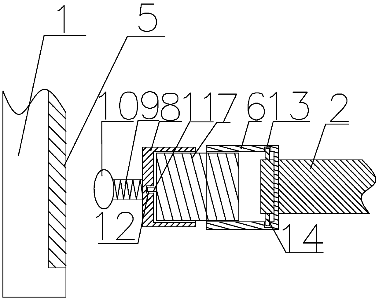
[0038] Based on the transformer-based radiator charged water flushing device, on the basis of Embodiment 1, a vertical chute 5 is provided on the vertical track 1, and the end of the horizontal track 2 connected to the chute 5 is provided with a connecting mobile device, which is connected The mobile device includes a first connecting post 6 with a cavity inside and openings at both ends, a second connecting post 7 with one end threaded inside the first connecting post 6 , and a third connecting post 8 connected with the other end of the second connecting post 7 And the pulley 10 connected on the third connecting column 8 drives the horizontal track 2 to slide up and down in the chute 5 through the pulley 10;
[0039] One end that the third connecting column 8 is connected with the second connecting column 7 is provided with a connecting groove for connecting the second connecting column 7, the inner bottom of the connecting groove is provided with a first groove 12, and the se...
Embodiment 3
[0043] Based on the transformer-based radiator charged water flushing device, on the basis of Embodiment 2, a first spring that can expand and contract along the direction of the horizontal track 2 is connected between the slider 3 and the vertical track 1, and under no external force, The first spring keeps the slider 3 at the center of the horizontal rail 2 . The upper and lower ends of the vertical track 1 are connected with horizontal retaining rods 4 . A second spring is connected between the stop bar 4 at the upper end of the vertical track 1 and the horizontal track 2, and without external force, the horizontal track 2 is positioned on the vertical line of the vertical track 1 under the action of the second spring.
PUM
 Abstract
Description
Claims
Application Information
 - R&D Engineer
- R&D Manager
- IP Professional
- Industry Leading Data Capabilities
- Powerful AI technology
- Patent DNA Extraction
Browse by: Latest US Patents, China's latest patents, Technical Efficacy Thesaurus, Application Domain, Technology Topic, Popular Technical Reports.
© 2024 PatSnap. All rights reserved.Legal|Privacy policy|Modern Slavery Act Transparency Statement|Sitemap|About US| Contact US: help@patsnap.com