
Wavefront sensor

A wavefront sensor and wavefront technology, applied in the direction of instruments, scientific instruments, measuring devices, etc., can solve the problem that the sensor is difficult to achieve spatial resolution, and achieve the effect of fewer optical components and a simple sensor structure

Pending Publication Date: 2019-03-26
UNIV OF SCI & TECH OF CHINA
View PDF1 Cites 9 Cited by
  • Summary
  • Abstract
  • Description
  • Claims
  • Application Information

AI Technical Summary

Problems solved by technology

(2) Limitation of the spatial resolution of the Hartmann wavefront sensor
Therefore, from the analysis of traditional detection strategies, it is difficult for the Hartmann wavefront sensor to achieve the pixel-level spatial resolution
Improving the measurement accuracy of the Hartmann wavefront sensor has become a research hotspot. Current solutions often increase the accuracy of wavefront restoration by increasing the complexity of devices and algorithms, but they cannot break through this fundamental limitation.

Method used


Image

  • Wavefront sensor
  • Wavefront sensor
  • Wavefront sensor

Examples


Embodiment Construction

[0015] The technical solutions in the embodiments of the present invention will be clearly and completely described below in conjunction with the accompanying drawings in the embodiments of the present invention. Obviously, the described embodiments are only some of the embodiments of the present invention, not all of them. Based on the embodiments of the present invention, all other embodiments obtained by persons of ordinary skill in the art without making creative efforts belong to the protection scope of the present invention.

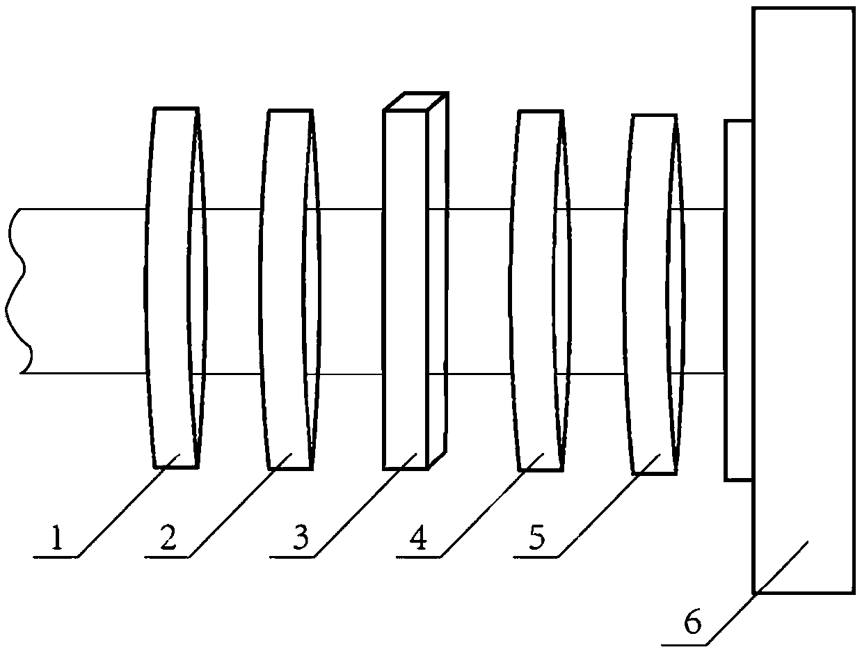
[0016] An embodiment of the present invention provides a wavefront sensor, such as figure 1 As shown, it mainly includes: a first polarizer 1, a half-wave plate 2, a calcite crystal 3, a quarter-wave plate 4, a second polarizer 5 and an array photodetector 6, and the above optical devices are sequentially connected , and the optical plane is perpendicular to the beam propagation direction.

[0017] Simultaneously:

[0018] The optical axis of the...


PUM


Abstract

The invention discloses a wavefront sensor. The wavefront sensor includes a first polarizing plate, a half wave plate, a calcite crystal, a quarter wave plate, a second polarizing plate and an array photodetector which are sequentially placed, wherein an optical surface of the device is perpendicular to the light beam spreading direction. The structure is simple, the quantity of optical elements is small, in combination with the present mature crystal growth and cutting process, batch production potential is achieved, moreover, the limitation of a lens array of the wavefront segmentation sampling element is eliminated by the wavefront sensor based on two-dimensional quantum weak measurement, pixel-level wavefront restoration accuracy is achieved, therefore, wavefront restoration of the ultra-high spatial frequency can be achieved, more importantly, the thinking formula of improving accuracy of wavefront restoration is broken, pursuing high-density sub-aperture arrangement and complex ultra-resolution algorithms is not needed, and the wavefront sensor is of great significance in the field of wavefront detection.

Description

technical field [0001] The invention relates to the technical field of optical information measurement and quantum precision measurement, in particular to a wavefront sensor. Background technique [0002] Wavefront sensing technology is a modern optical measurement technology. Through the sampling, modulation and detection of the far-field beam intensity distribution, the reconstruction and restoration of the wavefront phase is realized. It is widely used in wavefront correction, astronomical observation, medical imaging, laser technology and other fields. Typical wavefront sensors include shear interferometers, curvature wavefront sensors, and Hartmann wavefront sensors. These sensors have different characteristics and performance, suitable for different applications. Among them, the Hartmann wavefront sensor has high light energy utilization rate, strong anti-noise ability, simple and efficient, and real-time measurement, and has become one of the common wavefront sensor...

Claims


Application Information

Patent Timeline
IPC IPC(8): G01J9/00
CPCG01J9/00
Inventor 杨木刘正昊李强许金时李传锋
Owner UNIV OF SCI & TECH OF CHINA
Learn More