
Pole plate tunnel horizontal drying device

A technology of drying device and tunnel, which is applied in the direction of drying, drying machine, drying gas arrangement, etc., and can solve problems such as difficulty in ensuring the degree of drying of the plates, a large number of personnel and handling equipment, and uneven effect of the plates.

Pending Publication Date: 2019-03-26
广州市通上德智能装备有限公司
View PDF0 Cites 1 Cited by
  • Summary
  • Abstract
  • Description
  • Claims
  • Application Information

AI Technical Summary

Problems solved by technology

Domestic battery plates are dried in the form of a curing room. The plates are collected and put into the curing room. The drying time takes 2 to 3 days. The disadvantages of this drying method are: 1. The drying time is long and consumes 2. Due to the small air outlet at the connection with the air pump, only a certain position on the pole plate near the air outlet has a large air volume, and the air volume at other positions is small, so it is difficult to ensure that the two sides of the pole plate are The drying degree is the same, some places may have been dried, and some places are not dry; 3. Because a large number of plates are accumulated in the drying room, the temperature, humidity and wind flow of each position are different , so the effect of the dried plate is not uniform, and the surface and interior of the plate cannot be dried at the same time, which may easily lead to dry cracking of the plate; 4. It cannot be produced and used in time; 5. It requires a large number of personnel and handling equipment

Method used


Image

  • Pole plate tunnel horizontal drying device
  • Pole plate tunnel horizontal drying device
  • Pole plate tunnel horizontal drying device

Examples


Embodiment Construction

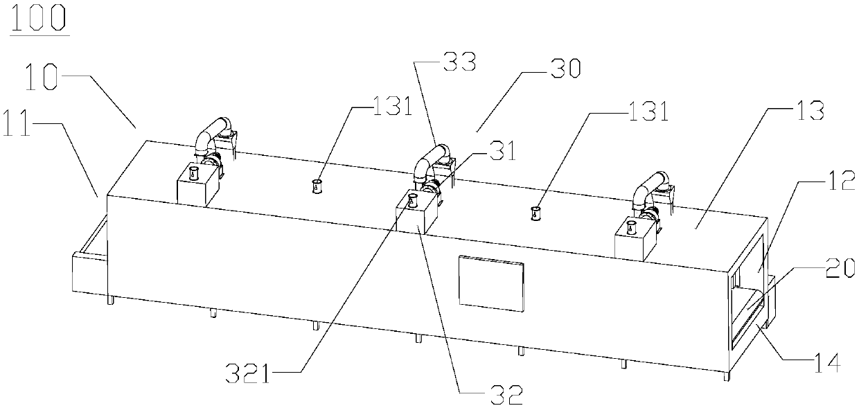
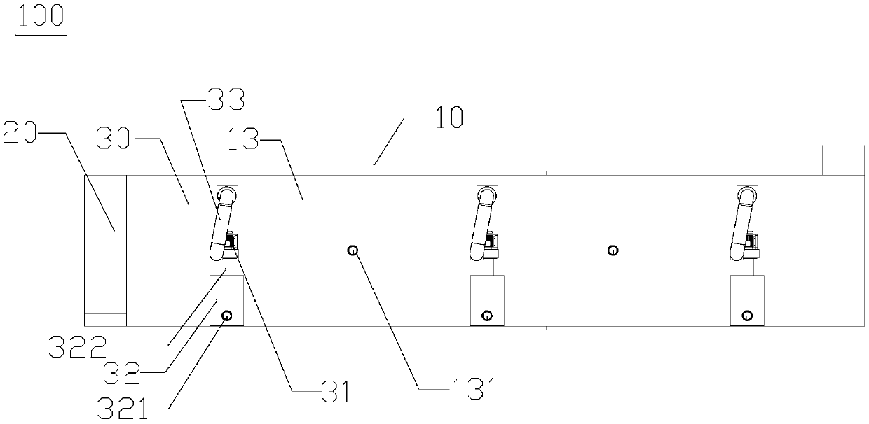
[0036] The following is attached Figure 1-6 The principles and features of the present invention are described, and the examples given are only used to explain the present invention, and are not used to limit the scope of the present invention. In the following paragraphs the invention is described more specifically by way of example with reference to the accompanying drawings. Advantages and features of the present invention will be apparent from the following description and claims. It should be noted that all the drawings are in a very simplified form and use imprecise scales, and are only used to facilitate and clearly assist the purpose of illustrating the embodiments of the present invention.

[0037] It should be noted that when a component is said to be "fixed" to another component, it can be directly on the other component or there can also be an intervening component. When a component is said to be "connected" to another component, it may be directly connected to th...


PUM


Abstract

The invention relates to a pole plate tunnel horizontal drying device. The pole plate tunnel horizontal drying device comprises a thermal insulation shell, a conveying belt device and air extraction circulating mechanisms; the thermal insulation shell is provided with a shell top plate and a shell bottom plate; and each air extraction circulating mechanism comprises a circulating fan, a heating box, an inlet air distribution plate and a return air distribution plate, the inlet air distribution plate is provided with first air distribution holes and second air distribution holes, the first airdistribution holes are located under a corresponding air feeding channel and are all formed in the middle of the inlet air distribution plate, the two sets of second air distribution holes are locatedon the two sides of the first air distribution holes correspondingly, and the first air distribution holes are smaller than the second air distribution holes. According to the pole plate tunnel horizontal drying device, due to the fact that air outlets at the second air feeding channels used for air feeding are small, the multiple first air distribution holes formed under the second air feeding channels can allow air to be fed easily, the second air distribution hole sets located on the two sides of the multiple first air distribution holes are difficult in air feeding, in order to ensure that the air feeding amount of the first air distribution holes and the air feeding amount of the second air distribution holes are basically the same, the areas of the first air distribution holes are smaller than those of the second air distribution holes correspondingly, and it is also ensured that the drying degrees of all portions of the two surfaces of a pole plate are the same.

Description

technical field [0001] The invention relates to the technical field of battery production, in particular to a horizontal drying device for a pole plate tunnel. Background technique [0002] "Horizontal battery" refers to a battery in a horizontal form. The positive and negative electrodes on each plate in the battery chip of the battery are distributed in the same plane in the form of rectangular blocks. During the production process of each polar plate, different types of lead pastes need to be brushed on both sides of the polar plate. The lead paste is wet when first applied and needs to be dried on both sides of the plate. Domestic battery plates are dried in the form of a curing room. The plates are collected and put into the curing room. The drying time takes 2 to 3 days. The disadvantages of this drying method are: 1. The drying time is long and consumes 2. Due to the small air outlet at the connection with the air pump, only a certain position on the pole plate near...

Claims


Application Information

Patent Timeline
IPC IPC(8): F26B15/18F26B25/06F26B21/00F26B21/04F26B21/06F26B25/00
CPCF26B15/18F26B21/001F26B21/004F26B21/04F26B21/06F26B25/00F26B25/06
Inventor 戴北平
Owner 广州市通上德智能装备有限公司
Learn More