
Evaporator and refrigeration system

A technology of evaporator and condenser, applied in the direction of evaporator/condenser, refrigerator, refrigeration components, etc., can solve the problems of increasing the height of the refrigeration system, large size of the air conditioner, reducing the size of the refrigeration system, etc., to improve the uniformity of heat exchange performance, close assembly relationship, and improve the effect of heat transfer

Pending Publication Date: 2019-03-26
SUZHOU BSE AIR CONDITIONER
View PDF10 Cites 0 Cited by
  • Summary
  • Abstract
  • Description
  • Claims
  • Application Information

AI Technical Summary

Problems solved by technology

[0004] However, in the actual installation process of the evaporator with this structure, since the air outlet is set on the top of the evaporator, the compressor is generally installed above the evaporator, so that the size of the entire air conditioner in the height direction is large and the occupied space is large. ; At the same time, since the liquid inlet is opened on the bottom of the cylinder, the condenser needs to be installed under the evaporator, otherwise the evaporator needs to be set up to make the liquid inlet of the evaporator leak outside, which is convenient for installing the pipeline on the The liquid inlet is connected to the condenser, which will also cause the height of the refrigeration system to increase, and the length of the connected pipeline is long, making the structure of the entire refrigeration system not compact; in addition, in the prior art, there is often an idle area in the shell of the condenser. Areas are also not being utilized
When assembling the refrigeration system, it is impossible to assemble the evaporator, compressor, and condenser as a whole to reduce the size of the refrigeration system, resulting in an uncompact structure of the refrigeration system

Method used


Image

  • Evaporator and refrigeration system
  • Evaporator and refrigeration system
  • Evaporator and refrigeration system

Examples


Embodiment 1

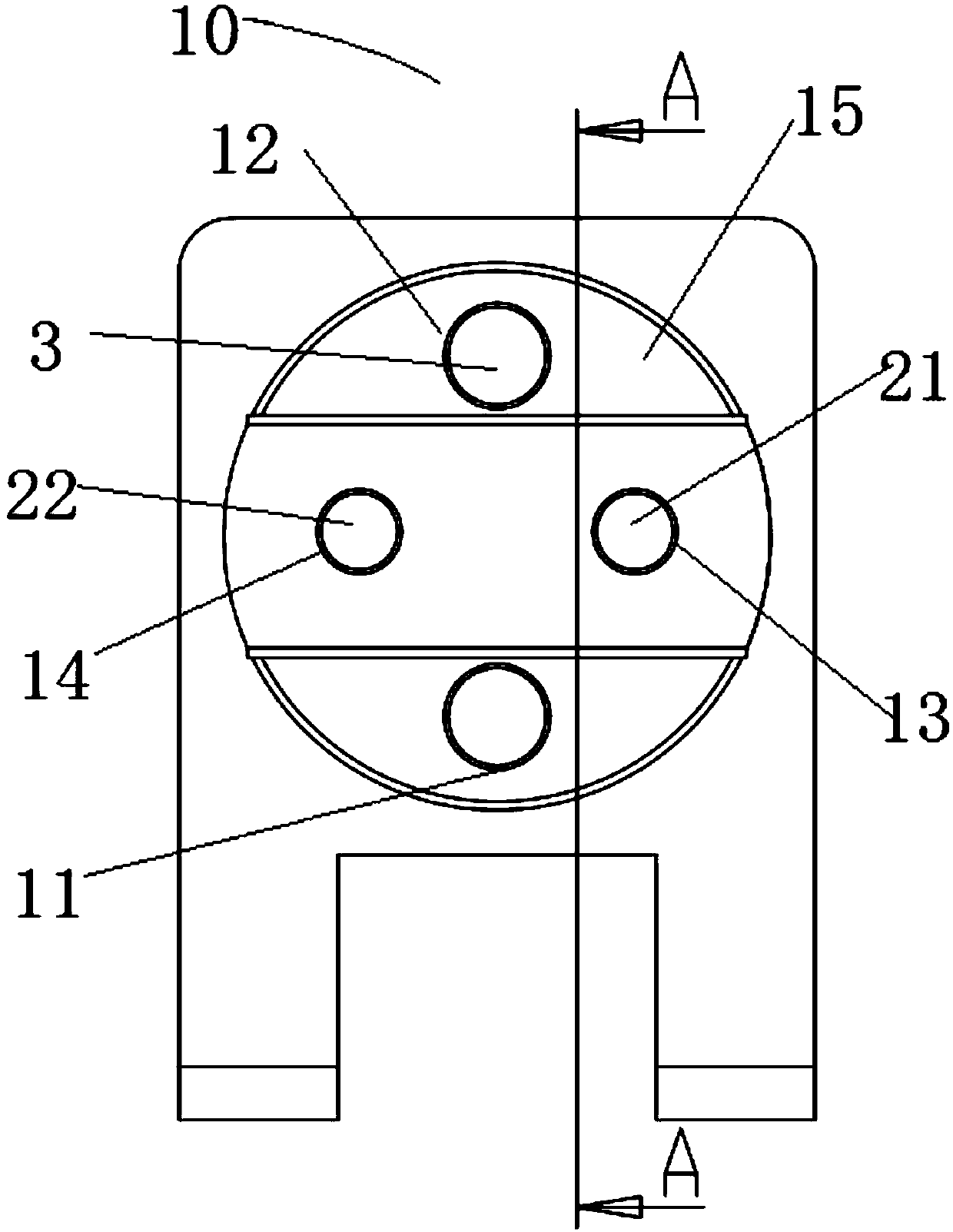
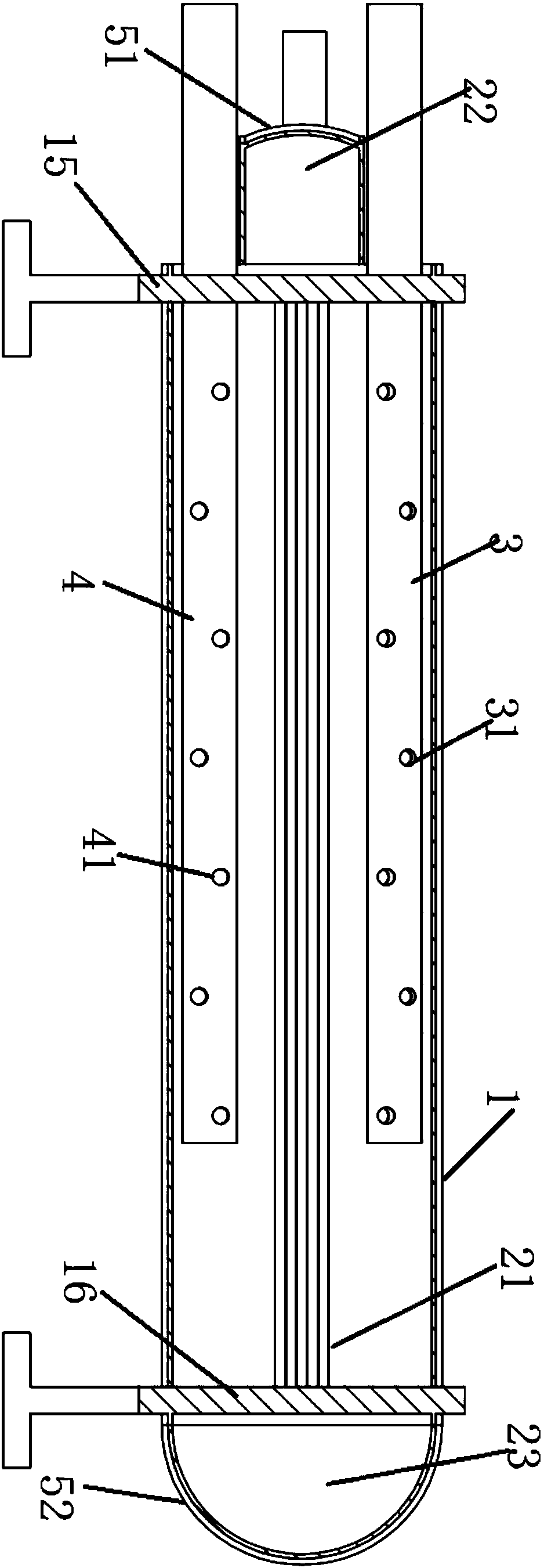
[0062] An evaporator is provided in this embodiment, such as figure 1 and figure 2 As shown, it includes a hollow cylinder 1, a heat exchange tube 2, an air collecting tube 3, and a distribution tube 4.

[0063] Wherein, the hollow cylinder 1 is arranged horizontally, and includes a body with a hollow inner cavity, and a first end plate 15 and a second end plate 16 installed on openings at both ends of the body. The first end plate 15 is provided with a first liquid inlet 11 , a first gas outlet 12 , a second liquid inlet 13 and a second liquid outlet 14 . The first gas outlet 12 is located above the first liquid inlet 11; along the vertical direction, the second liquid inlet 13 and the second liquid outlet 14 are located between the first gas outlet 12 and the first liquid inlet 11

[0064] The first end plate 15 is also provided with a first cover 51, for example, the first cover 51 is an arc-shaped plate, the first cover 51 is located between the first liquid inlet 11 an...

Embodiment 2

[0072] This embodiment provides an evaporator, which is different from the evaporator 10 provided in Embodiment 1 in that:

[0073] The suction port 31 on the gas collecting pipe 3 is not only set on the top of the gas collecting pipe 3, but also can be set on any wall surface of the gas collecting pipe 3. During the gas rising process, the effect of gas-liquid separation can still be achieved under the weight of the liquid itself. .

[0074] As a first alternative embodiment, the number of air inlets 31 can also be one, two, three, four, five, etc., the more the number of air inlets 31 is set, the cooling can be timely The gas formed by the refrigerant is pumped into the gas collecting pipe 3; the smaller the number of suction ports 31 is set, the time required for the gas formed by the refrigerant to be pumped into the gas collecting pipe 3 is relatively long, and the specific number of settings depends on the actual use .

[0075] As a further alternative embodiment, the fi...

Embodiment 3

[0077] This embodiment provides an evaporator, which is different from the evaporator 10 provided in Embodiment 1 or Embodiment 2 in that:

[0078] The location of the opening of the liquid distribution port 41 is different, and the opening direction of the liquid distribution port 41 may not face the side of the heat exchange tube 2; the adjacent liquid distribution ports 41 may also be located at the same height, or arranged in a disorderly manner. The distribution pipe 4 is provided with a liquid dispensing port 41 , so that the refrigerant can be sprayed into the inner cavity of the cylinder body 1 to exchange heat with the solution in the heat exchange pipe 2 .

[0079] As a first alternative embodiment, the number of liquid distribution ports can be one, two, three, four, five, etc., only need to inject the refrigerant in the distribution pipe 4 into the cylinder 1 in the cavity. The specific number of settings depends on the actual usage.

[0080] As a further alterna...


PUM


Abstract

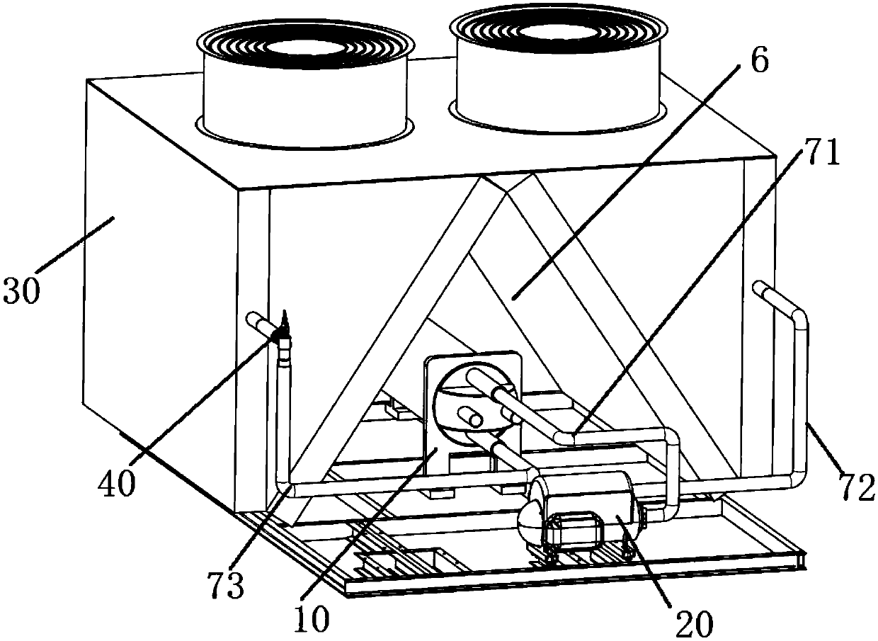
The invention discloses an evaporator and a refrigeration system. The evaporator comprises a hollow cylinder and a heat exchange tube. The hollow cylinder is horizontally arranged, and a first liquidinlet, a first air outlet, a second liquid inlet and a second liquid outlet are formed in the end surface of the cylinder; and the two ends of the heat exchange tube are separately connected to the second liquid inlet and the second liquid outlet. The refrigeration system includes a compressor, the evaporator, a condenser with an idle area and a throttling device. When the evaporator is assembledwith the compressor and the condenser, since the first liquid inlet and the first air outlet are both formed in the end surface of the cylinder, the compressor and the evaporator are horizontally disposed; the compressor and the evaporator are both installed in the idle area in a condenser shell, the evaporator, the compressor and the condenser are assembled in one shell, so that the size of the refrigeration system is the size of an original condenser, and the height is only the original size of the condenser; the entire refrigeration system is compact in structure, and the occupied space issmall; and meanwhile, the refrigeration system can further be moved conveniently.

Description

technical field [0001] The invention belongs to the technical field of air conditioning, and in particular relates to an evaporator and a refrigeration system. Background technique [0002] The air conditioner in the prior art mainly includes a compressor, an evaporator, a condenser connected in sequence through pipelines, and the condenser is connected to the evaporator again, and the refrigerant circulates in the pipelines to realize the process of cooling or heating. The structure of the evaporator in the prior art is mostly such as the evaporator disclosed in the Chinese patent document CN205784014U, which mainly includes a horizontally arranged cylinder, a heat exchange tube installed horizontally in the cylinder, and vertically arranged at the bottom of the cylinder The liquid inlet on the top, and the liquid inlet pipe installed on the liquid inlet; the gas outlet on the top of the cylinder is opened in the vertical direction, and the gas outlet is provided with a gas...

Claims


Application Information

Patent Timeline
Patent Type & Authority Applications(China)
IPC IPC(8): F25B39/02F25B39/04
CPCF25B39/02F25B39/028F25B39/04F25B2339/0242
Inventor 查晓冬
Owner SUZHOU BSE AIR CONDITIONER
Learn More