LED lamp convenient to mount and dismount
A technology of LED lamps and LED lamps, which is applied to the components of lighting devices, lighting devices, fixed lighting devices, etc., can solve problems such as potential safety hazards, cumbersome installation operations, and electric shock accidents for staff, and achieve installation and disassembly, and reduce The effect of production cost and power saving
- Summary
- Abstract
- Description
- Claims
- Application Information
AI Technical Summary
Problems solved by technology
Method used
Image
Examples
specific Embodiment approach 1
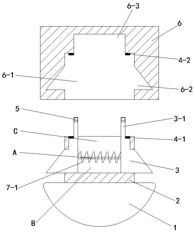
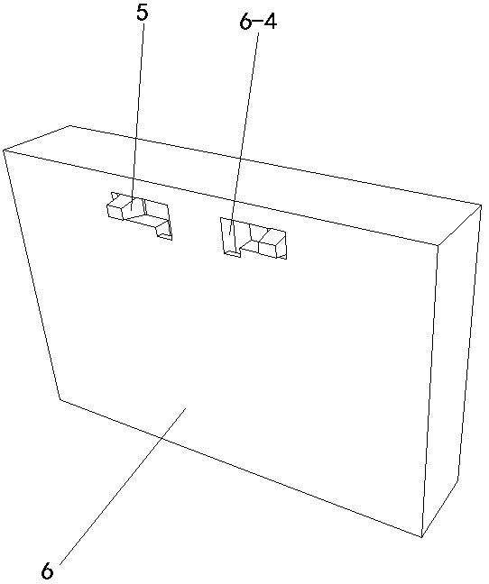
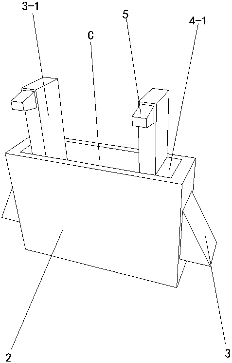
[0012] Specific implementation mode one: as Figure 1~Figure 5 As shown, the present invention discloses an LED lamp that is easy to install and disassemble, including an LED lamp body 1, a mounting block 2, a mounting frame 6, a spring 7-1, two clamping blocks 3, and two lower metal sheets 4- 1. Two upper metal sheets 4-2 and two movable bumps 5. The upper end of the LED lamp body 1 is fixedly connected to the lower end of the mounting block 2. The mounting block 2 is provided with a through hole B running through it in the transverse direction. The upper surface of the block 2 is provided with a sinking cavity C, and the sinking cavity C is connected to the through hole B. The two ends of the sinking cavity C are respectively provided with a clamping block 3, and the outer end of each clamping block 3 Both are inclined and protrude out of the through hole B. The two blocks 3 are connected by a spring 7-1. The upper end of each block 3 is provided with an extension 3-1 and a ...
specific Embodiment approach 2
[0013] Specific implementation mode two: as Figure 5 As shown, this embodiment is a further description of Embodiment 1. The upper end of the front of each extension 3-1 is provided with a groove 4 6-4, and one end of the movable protrusion 5 is inserted in a gap In the groove four 6-4, one end of the movable protrusion 5 is fixedly connected with one end of the spring two 7-2, and the other end of the spring two 7-2 is fixedly connected with the inner sidewall of the groove four 6-4.
specific Embodiment approach 3
[0014] Specific implementation mode three: as Figure 1~Figure 5 As shown, this embodiment is a further description of Embodiment 1 or Embodiment 2. The upper and lower sides of the outer end of the movable protrusion 5 are inclined surfaces.
PUM
 Abstract
Description
Claims
Application Information
 - R&D Engineer
- R&D Manager
- IP Professional
- Industry Leading Data Capabilities
- Powerful AI technology
- Patent DNA Extraction
Browse by: Latest US Patents, China's latest patents, Technical Efficacy Thesaurus, Application Domain, Technology Topic, Popular Technical Reports.
© 2024 PatSnap. All rights reserved.Legal|Privacy policy|Modern Slavery Act Transparency Statement|Sitemap|About US| Contact US: help@patsnap.com


