
A long-term deodorant floor drain structure

A floor drain and anti-odor technology, which is applied in the field of sanitary products, can solve the problems of poor anti-odor performance and inability to deodorize for a long time, and achieve the effect of preventing odor from escaping, preventing blockage, and good collection effect

Active Publication Date: 2020-06-30
ZHEJIANG SCI-TECH UNIV
View PDF7 Cites 2 Cited by
  • Summary
  • Abstract
  • Description
  • Claims
  • Application Information

AI Technical Summary

Problems solved by technology

[0003] In order to solve the problem of poor deodorization performance and inability to deodorize long-term deodorization in the floor drain in the prior art, the present invention provides a long-term deodorization type floor drain structure, which can be mechanically sealed when the water in the water-sealed cup is evaporated, thereby achieving Long-lasting deodorant effect

Method used


Image

  • A long-term deodorant floor drain structure
  • A long-term deodorant floor drain structure
  • A long-term deodorant floor drain structure

Examples


Embodiment 1

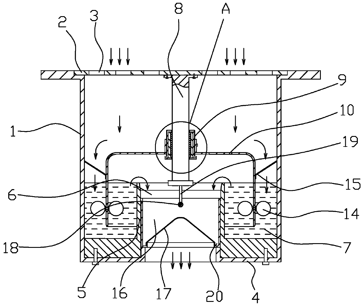
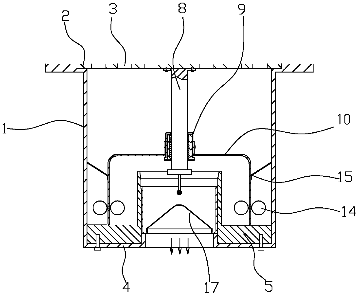
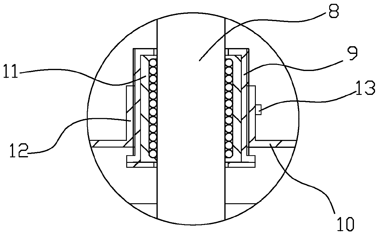
[0026] Embodiment 1: as figure 1 , figure 2 , image 3 with Figure 8 A long-term anti-odor type floor drain structure is shown, including a floor drain housing 1 and a cover body 2, the cover body is provided with a number of water inlet holes 3, the lower end of the floor drain housing is provided with a support ring 4, and the upper side of the support ring is fixed with a ring The water seal cup 5, the center of the water seal cup is provided with a liquid outlet channel 6, an annular cavity 7 is formed between the water seal cup and the inner wall of the shell, a vertical slide bar 8 is fixed at the center of the bottom surface of the cover body, and a vertical slide bar 8 is fixed on the slide bar. There is a sliding sleeve 9, the outer side of the sliding sleeve is fixed with an isolation cover 10 with the opening facing downward, the opening end of the isolation cover stretches into the annular cavity, a linear bearing 11 is arranged between the sliding sleeve and t...

Embodiment 2

[0030] Embodiment 2: as Figure 4 with Figure 5A long-term anti-odor type floor drain structure is shown, including a floor drain housing 1 and a cover body 2. The cover body is provided with a number of water inlet holes 3, and the lower end of the floor drain housing is provided with a support ring 4, and a ring is fixed on the upper side of the support ring. Shaped water seal cup 5, the center of the water seal cup is provided with a liquid outlet channel 6, an annular cavity 7 is formed between the water seal cup and the inner wall of the shell, a vertical slide bar 8 is fixed at the center of the bottom surface of the cover body, and a vertical slide bar 8 is fixed on the slide bar A sliding sleeve 9 is provided, and the outer side of the sliding sleeve is fixed with an isolation cover 10 with the opening facing downwards, and the opening end of the isolation cover stretches into the annular cavity, such as image 3 As shown, a linear bearing 11 is provided between the ...


PUM


Abstract

The invention relates to the technical field of sanitary products, and discloses a long-acting anti-odor type floor drain structure, which includes a floor drain shell and a cover body. The cover body is provided with a water inlet hole, and the lower end of the floor drain shell is provided with a support ring. An annular water seal cup is fixed on the upper side of the support ring, the center of the water seal cup is provided with a liquid outlet channel, an annular cavity is formed between the water seal cup and the inner wall of the shell, and the center of the bottom surface of the cover is fixed with a A vertical slide bar, the slide bar is provided with a sliding sleeve, the outer side of the sliding sleeve is fixed with an isolation cover facing the opening, the opening end of the isolation cover extends into the annular cavity, and the inner wall of the isolation cover 1. A number of floating balls are evenly fixed on the outer wall at the same height. The invention has the beneficial effects of being able to maintain long-term sealing and effectively preventing the odor from escaping from the sewer.

Description

technical field [0001] The invention relates to the technical field of sanitary products, in particular to a long-acting deodorant floor drain structure. Background technique [0002] The floor drain is an important interface connecting the drainage pipe system and the indoor floor. As an important part of the drainage system in the residence, its performance directly affects the quality of the indoor air, and is very important for the odor control in the bathroom. The floor drain should have two basic functions: first, to ensure smooth drainage and to quickly remove the accumulated water on the ground; second, to have good sealing performance and to effectively prevent the odor in the sewer from entering the room. Current floor drains usually adopt a water seal structure. However, if the floor drain is not connected to water for a long time, the water at the water seal will evaporate, causing the odor in the sewer to enter the room. Contents of the invention [0003] In ...

Claims


Application Information

Patent Timeline
Patent Type & Authority Patents(China)
IPC IPC(8): E03F5/04
CPCE03F5/0407
Inventor 宋瑾钰
Owner ZHEJIANG SCI-TECH UNIV
Learn More