
Speed limiting type reversing control system

A technology of control system and control unit, which is applied in control/adjustment system, speed/acceleration control, control device, etc., can solve the problems of limited field of vision, large blind spot for reversing, easy to misuse, etc., to improve safety and low cost , the effect of simple structure

Pending Publication Date: 2019-03-26
CHANGCHUN UNIV OF TECH
View PDF5 Cites 4 Cited by
  • Summary
  • Abstract
  • Description
  • Claims
  • Application Information

AI Technical Summary

Problems solved by technology

[0002] With the rapid development of science and technology and the continuous improvement of living standards, cars have become a must-have for ordinary families, bringing a lot of convenience to people's life and work, but they have also caused many traffic accidents during people's use. Among them, collisions and scratching accidents with rear obstacles (pedestrians, vehicles, walls, etc. that hinder reversing) are more common when reversing. This is due to the limited vision of the driver when reversing, the large blind spot for reversing, and easy misuse. Caused by the reason; the existing reversing radar and reversing image technology can only prompt the driver through voice and video, but cannot realize active speed limit to prevent problems such as excessive driving speed and accidental stepping on the accelerator during the reversing process
[0003] In the existing patent application number 201520030226.6, a vehicle constant speed reversing system is disclosed. When the vehicle needs to reverse at a stable speed, the driver can manually close the first switch. The acceleration information is transmitted to the controller. At this time, the controller cuts off the connection between the accelerator pedal and the throttle by disconnecting the second switch, and controls the opening of the throttle to make the car reverse at a fixed speed, reducing the driver's operating burden. , but in this system, the reversing speed is always fixed, which cannot meet the changing working conditions of reversing

Method used


Image

  • Speed limiting type reversing control system
  • Speed limiting type reversing control system
  • Speed limiting type reversing control system

Examples


Embodiment Construction

[0011] In order to deepen the understanding of the present invention, the present invention will be further described below in conjunction with the accompanying drawings.

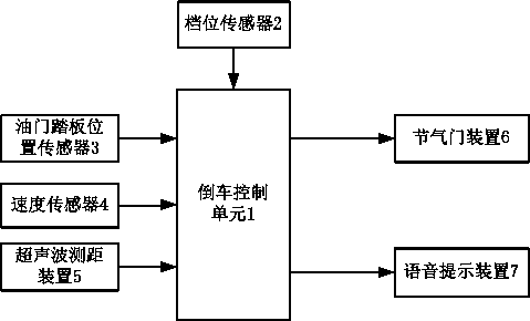
[0012] Such as figure 1 As shown, a speed-limiting reversing control system mainly includes a reversing control unit 1, a gear position sensor 2, an accelerator pedal position sensor 3, a speed sensor 4, an ultrasonic distance measuring device 5, a throttle device 6, and a voice prompt device 7, The input end of the reversing control unit 1 is respectively connected with the gear position sensor 2 installed near the transmission to detect the gear position information of the transmission, and is connected with the accelerator pedal position sensor 3 installed on the accelerator pedal to detect the position information of the accelerator pedal. The speed sensor 4 on the transmission is connected to detect the driving speed of the vehicle, and is connected to the ultrasonic distance measuring device 5 install...


PUM


Abstract

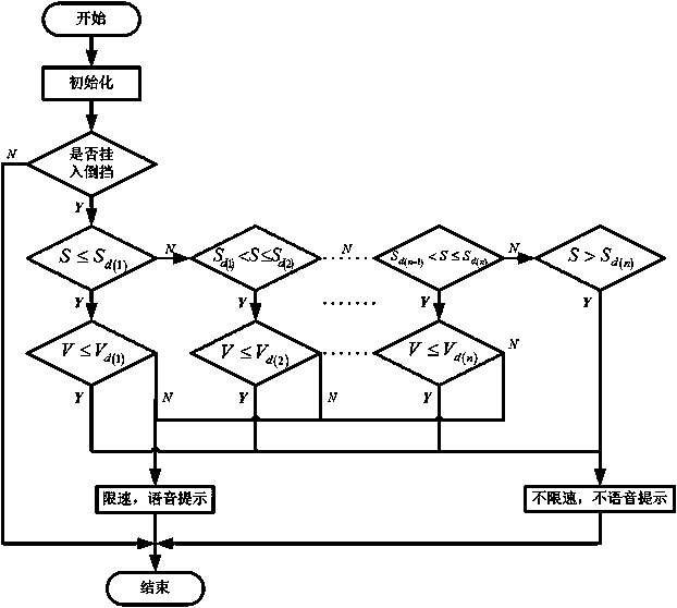
The invention discloses a speed limiting type reversing control system. The speed limiting type reversing control system mainly comprises a reversing control unit, a gear position sensor, an accelerator pedal position sensor, a speed sensor, an ultrasonic ranging device, a throttle valve device and a speech prompt device. The reversing control unit compares the actual distance, detected by the ultrasonic ranging device, from a barrier behind a vehicle and the vehicle traveling speed detected by the speed sensor with the safety distance and the highest safety speed stored in the reversing control unit correspondingly, then controls the throttle valve device at the output end to conduct active speed limiting on the vehicle and controls the voice prompt device mounted on a center console to give a voice prompt to a driver. Through the speed limiting type reversing control system, collision and scratch accidents caused by the problems such as too high reversing speed and accelerator pedalmisapplication of the vehicle can be prevented, and the reversing safety is improved. Meanwhile, the speed limiting type reversing control system is low in cost, simple in structure, convenient to useand practical.

Description

technical field [0001] The invention relates to the field of automobiles, in particular to a speed-limiting reversing control system. Background technique [0002] With the rapid development of science and technology and the continuous improvement of living standards, cars have become a must-have for ordinary families, bringing a lot of convenience to people's life and work, but they have also caused many traffic accidents during people's use. Among them, collisions and scratching accidents with rear obstacles (pedestrians, vehicles, walls, etc. that hinder reversing) are more common when reversing. This is due to the limited vision of the driver when reversing, the large blind spot for reversing, and easy misuse. The reason is that the existing reversing radar and reversing image technology can only prompt the driver through voice and video, but cannot realize active speed limit, so as to prevent problems such as excessive driving speed and accidental stepping on the accele...

Claims


Application Information

Patent Timeline
IPC IPC(8): B60K31/02B60Q5/00
CPCB60K31/02B60Q5/005B60K2031/0091B60K2031/0016
Inventor 崔高健宁方虎李绍松李增吴晓东商小强王帅田云胜王书君
Owner CHANGCHUN UNIV OF TECH
Learn More