
An auxiliary device for laying cables

An auxiliary device and cable laying technology, applied in the direction of cable laying equipment, etc., can solve the problems of high work efficiency, inability to hoist cables, etc., and achieve the effect of high work efficiency, avoiding dust corrosion, and avoiding tilting

Active Publication Date: 2020-05-19
STATE GRID SHANDONG ELECTRIC POWER +1
View PDF6 Cites 0 Cited by
  • Summary
  • Abstract
  • Description
  • Claims
  • Application Information

AI Technical Summary

Problems solved by technology

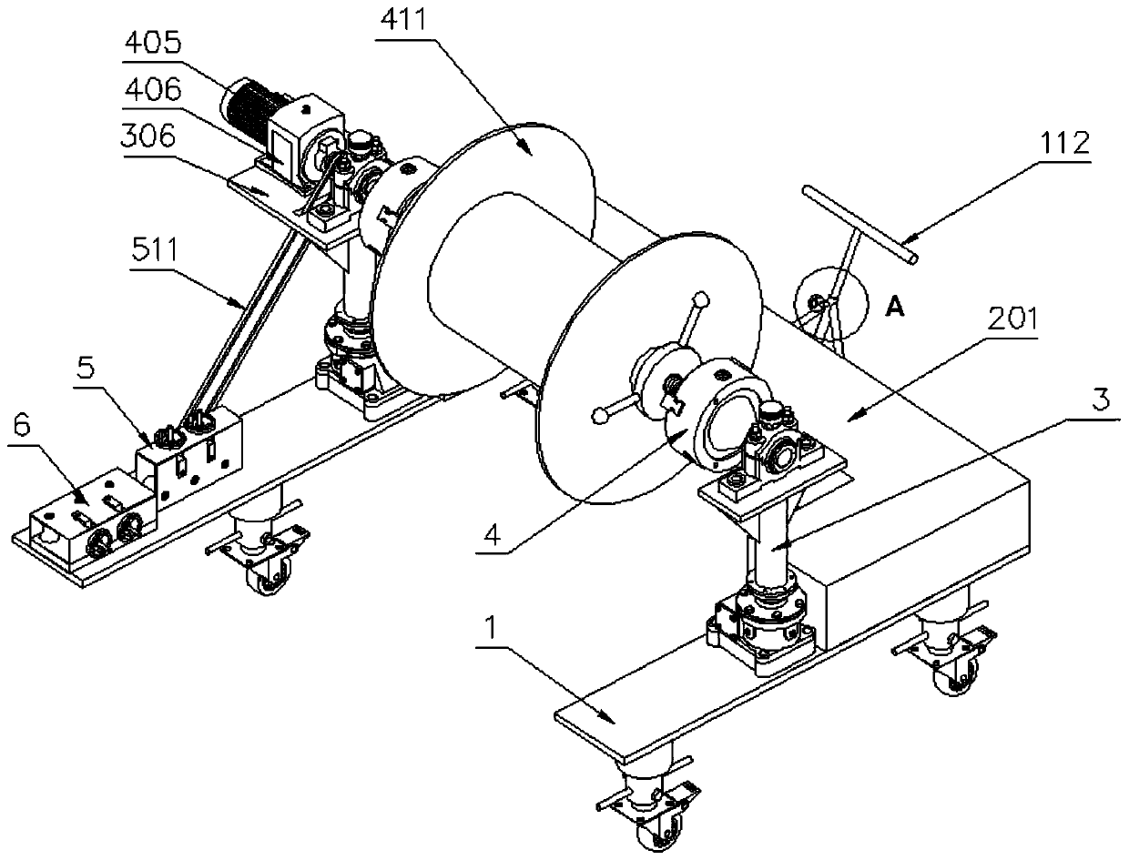
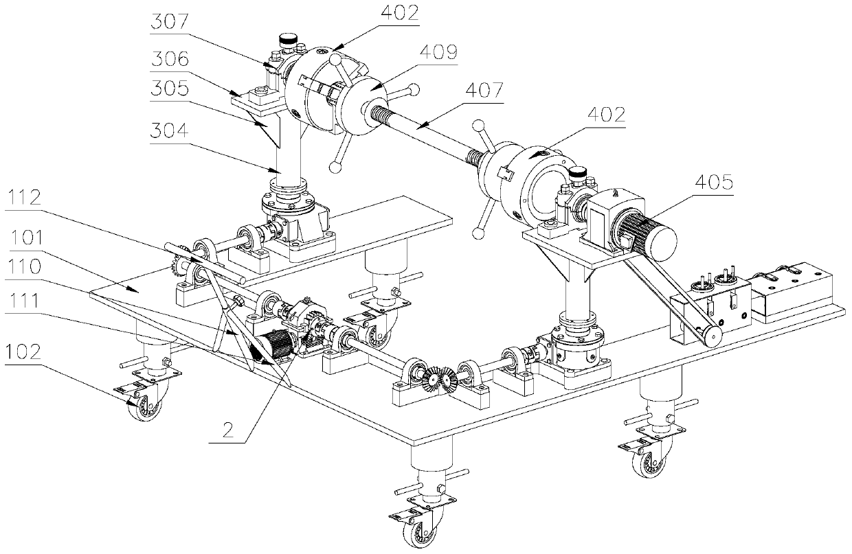
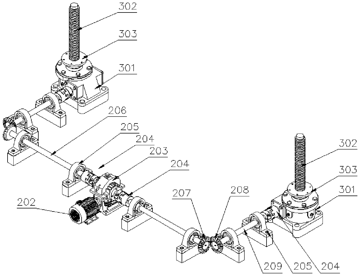
[0003] The purpose of the present invention is to overcome the deficiencies in the prior art and provide a cable laying auxiliary device, which solves the problem that the hoisting vehicle cannot be hoisted for laying in a small space area, and the device adopts an integrated structure, and one person can complete the operation , high work efficiency; and the lifting device adopts a linkage method, and the lifting rate is consistent, which avoids the tilting of the cable drum

Method used


Image

  • An auxiliary device for laying cables
  • An auxiliary device for laying cables
  • An auxiliary device for laying cables

Examples


Embodiment Construction

[0040] The following will be combined with Figure 1-10 , clearly and completely describe the technical solutions in the embodiments of the present invention, obviously, the described embodiments are only some of the embodiments of the present invention, not all of them. Based on the embodiments of the present invention, all other embodiments obtained by persons of ordinary skill in the art without making creative efforts belong to the protection scope of the present invention.

[0041] In describing the present invention, it should be understood that the terms "longitudinal", "transverse", "upper", "lower", "front", "rear", "left", "right", "vertical", The orientations or positional relationships indicated by "horizontal", "top", "bottom", "inner", "outer", etc. are based on the orientations or positional relationships shown in the drawings, and are only for the convenience of describing the present invention, rather than indicating or It should not be construed as limiting ...


PUM


Abstract

The invention discloses a cable laying assisting device. One side of a transmission motor is provided with a double-headed reducer; one end of each first transmission shaft is provided with a drivinggear; one end of each second transmission shaft is provided with a driven gear that is engaged with the corresponding driving gear; one side of each second transmission shaft is provided with a lifting device; the input shaft of each screw jack is connected with the corresponding second transmission shaft through a coupling; the upper part of each screw sleeve I is provided with a screw sleeve III; the upper parts of the supporting plates is provided with a rotating device; the rotating device comprises bearing seats II, rotating shafts I, chucks, and a rotating shaft II; the bearing seats IIare fixedly mounted on the upper parts of the supporting plates respectively; the bearing seats II are internally provided with bearings respectively; the rotating shafts I are installed in bearing inner rings inside the bearing seats II respectively; one end of each rotating shaft I is fixedly connected with the corresponding chuck; and two ends of the rotating shaft II are respectively installedinside the chucks at two sides. The cable laying assisting device of the invention is of an integrated structure. With the cable laying assisting device adopted, operation can be completed by one person, so that work efficiency is high; and the lifting device adopts a linkage manner, and the lifting rate of the lifting device is uniform, and therefore, the inclination of a cable reel can be avoided.

Description

technical field [0001] The invention belongs to the technical field of electric equipment, and in particular relates to a cable laying auxiliary device. Background technique [0002] Cable laying is an important link in the process of electric power construction. When laying large-scale cables, due to the weight of the cable reel more than ten tons, it is often necessary to use special hoisting tools for construction. However, for areas with small space or rough roads, hoisting vehicles It is impossible to drive in, which makes the laying of cables more difficult; in order to solve this problem, the research and development personnel designed a cable laying auxiliary frame, which uses screw rods or hydraulic lifting to lift the cable coils for laying construction. The split design is adopted. When using, two sets of auxiliary racks need to be placed on both sides of the cable tray, and then the cable tray is lifted by the lifting device; the following problems exist in the u...

Claims


Application Information

Patent Timeline
Patent Type & Authority Patents(China)
IPC IPC(8): H02G1/06
CPCH02G1/06
Inventor 于光远尹爱辉王宝勇李静秦昌龙刘思华
Owner STATE GRID SHANDONG ELECTRIC POWER
Learn More