
Power connector and connector assembly

A technology for power connectors and connector assemblies, applied in conductive connections, parts of connecting devices, connections, etc., can solve problems affecting safety, thermal welding, thermal melting of positive conductive terminals and negative conductive terminals, etc. Strength, effect of reliable electrical contact

Active Publication Date: 2019-03-22
TYCO ELECTRONICS (SHANGHAI) CO LTD
View PDF5 Cites 15 Cited by
  • Summary
  • Abstract
  • Description
  • Claims
  • Application Information

AI Technical Summary

Problems solved by technology

However, when plugging and unplugging with power, an arc will be generated between the positive conductive terminal and the positive bus bar and between the negative conductive terminal and the negative bus bar. When the power supply voltage is high, the high-voltage arc generated may burn the positive conductive terminal and the negative bus bar. Negative conductive terminals, in severe cases, may cause thermal fusion of positive conductive terminals and negative conductive terminals, making positive conductive terminals and negative conductive terminals thermally welded with positive bus bars and negative bus bars, seriously affecting safety

Method used


Image

  • Power connector and connector assembly
  • Power connector and connector assembly
  • Power connector and connector assembly

Examples


Embodiment Construction

[0036] The technical solutions of the present invention will be further specifically described below through the embodiments and in conjunction with the accompanying drawings. In the specification, the same or similar reference numerals designate the same or similar components. The following description of the embodiments of the present invention with reference to the accompanying drawings is intended to explain the general inventive concept of the present invention, but should not be construed as a limitation of the present invention.

[0037] In addition, in the following detailed description, for purposes of explanation, numerous specific details are set forth in order to provide a comprehensive understanding of the embodiments of the present disclosure. It may be evident, however, that one or more embodiments may be practiced without these specific details. In other instances, well-known structures and devices are shown in diagrammatic form to simplify the drawings.

[003...


PUM


Abstract

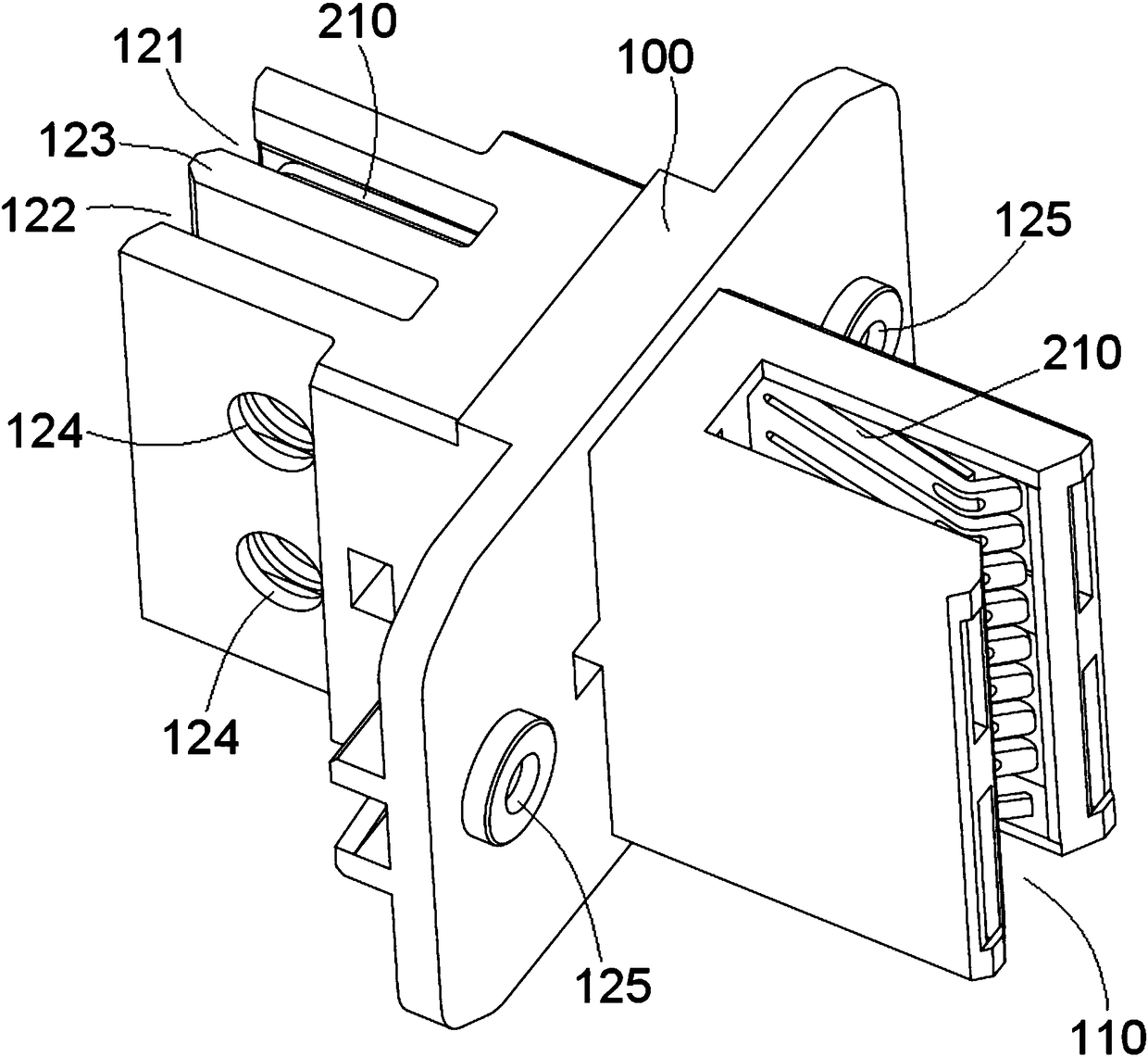
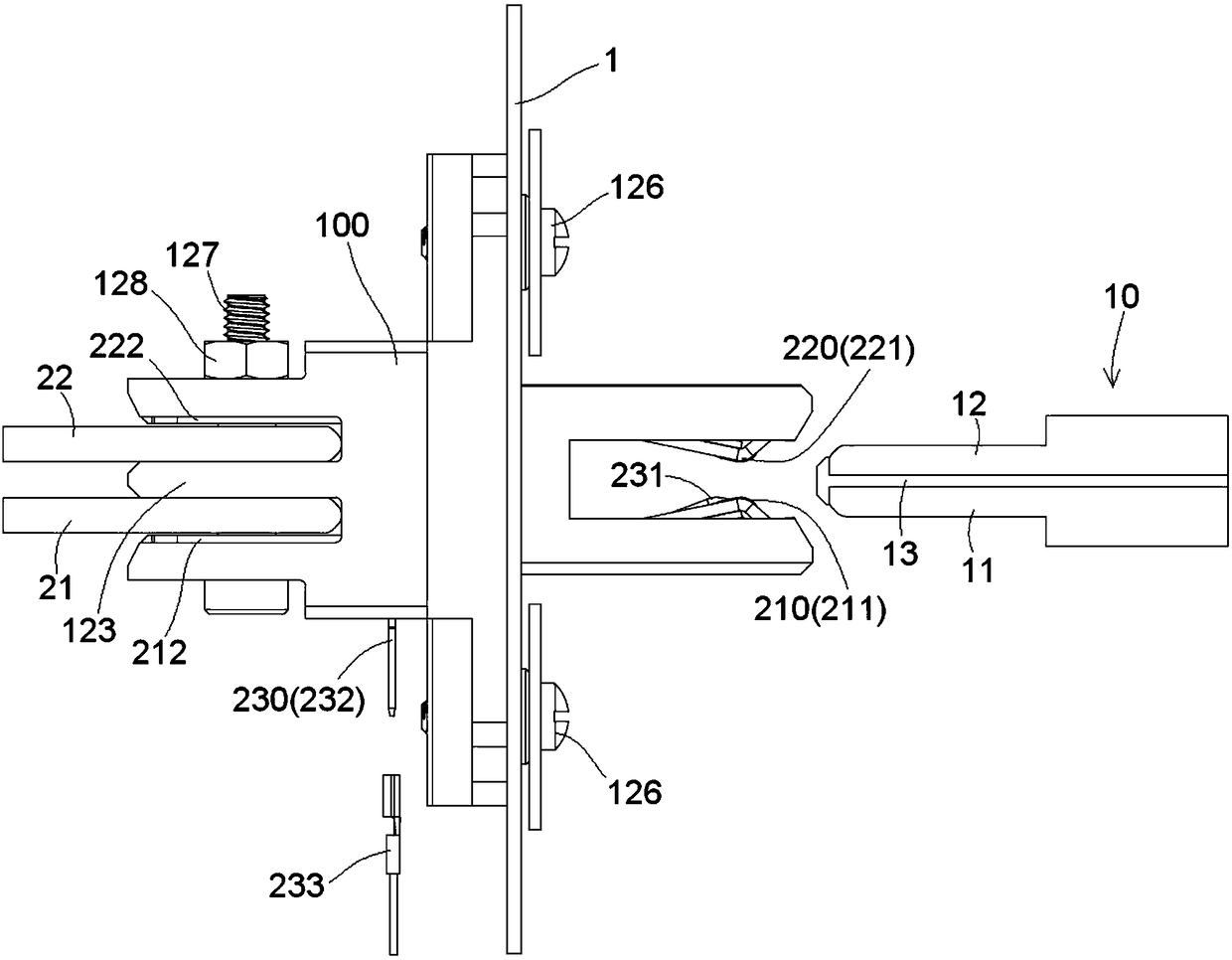
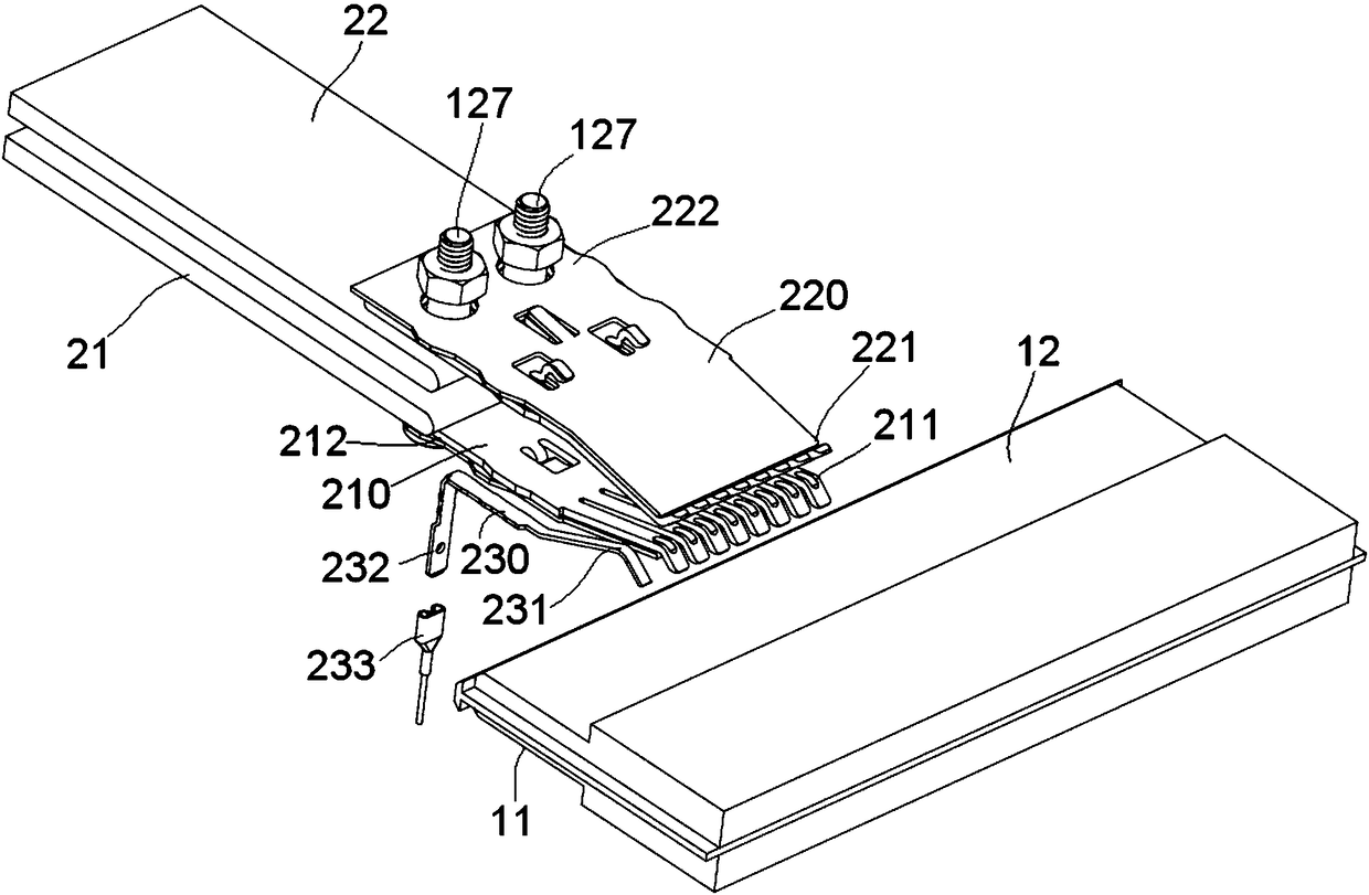
The invention discloses a power connector, which comprises an insulating body with a slot formed in one side thereof, and conductive terminals arranged in the insulating body. Each conductive terminalhas an electrical contact at one end thereof, which is suitable for being in electrical contact with a bus-bar plug assembly inserted into the slot. The power connector further comprises a detectionterminal arranged in the insulating body. The detection terminal has an electrical contact at one end thereof, which is suitable for being in electrical contact with the bus-bar plug assembly insertedinto the slot. The electrical contact of the detection terminal is located at the back of the electrical contacts of the conductive terminals, so that the detection terminal electrically contacts thebus-bar plug assembly after the conductive terminals electrically contact the bus-bar plug assembly in the process in which the bus-bar plug assembly is inserted. Thus, the on / off time of a power supply system can be controlled according to the electrical connection state of the detection terminal. Therefore, electric arc between the conductive terminals and the bus-bar plug assembly is avoided during plugging and pulling of the bus-bar plug assembly, and the safety performance of the power connector is improved.

Description

technical field [0001] The invention relates to a power connector and a connector assembly including the power connector. Background technique [0002] In the prior art, a power connector generally includes an insulating body and a positive conductive terminal and a negative conductive terminal disposed in the insulating body. The positive conductive terminal and the negative conductive terminal are adapted to make electrical contact respectively with a positive bus bar and a negative bus bar inserted into the power connector. However, when plugging and unplugging with power, an arc will be generated between the positive conductive terminal and the positive bus bar and between the negative conductive terminal and the negative bus bar. When the power supply voltage is high, the high-voltage arc generated may burn the positive conductive terminal and the negative bus bar. The negative conductive terminal may cause heat fusion of the positive conductive terminal and the negati...

Claims


Application Information

Patent Timeline
Patent Type & Authority Applications(China)
IPC IPC(8): H01R13/11H01R13/631H01R24/00
CPCH01R13/112H01R13/113H01R13/6315H01R24/00H01R13/02H01R2103/00H01R4/46H01R13/187H01R13/26H01R13/6215H01R25/162H01R12/7088H01R9/223
Inventor 刘娇勇赵光明李华
Owner TYCO ELECTRONICS (SHANGHAI) CO LTD
Learn More