
Switch cabinet assembly and mechanical and electrical interlocking device thereof

A technology of electrical interlocking and switchgear, applied in the field of power switchgear, can solve problems such as inconsistency between mechanical operation and electrical operation, damage to the mechanism, and influence on power supply, and achieve the effect of avoiding damage to the mechanism or affecting power supply

Pending Publication Date: 2019-03-22
XUJI GRP +2
View PDF0 Cites 1 Cited by
  • Summary
  • Abstract
  • Description
  • Claims
  • Application Information

AI Technical Summary

Problems solved by technology

[0004] The purpose of the present invention is to provide a mechanical and electrical interlocking device to solve the problem that the inconsistency between the mechanical operation and the electrical operation causes damage to the mechanism or affects the power supply when the three-out two interlock of the switch cabinet in the prior art; the purpose of the present invention is also to A switch cabinet assembly is provided to solve the problem in the prior art that the mechanism is damaged or the power supply is affected due to the inconsistency between the mechanical operation and the electrical operation when the switch cabinet is interlocked from three to two

Method used


Image

  • Switch cabinet assembly and mechanical and electrical interlocking device thereof
  • Switch cabinet assembly and mechanical and electrical interlocking device thereof
  • Switch cabinet assembly and mechanical and electrical interlocking device thereof

Examples


Embodiment Construction

[0023] Embodiments of the present invention will be further described below in conjunction with the accompanying drawings.

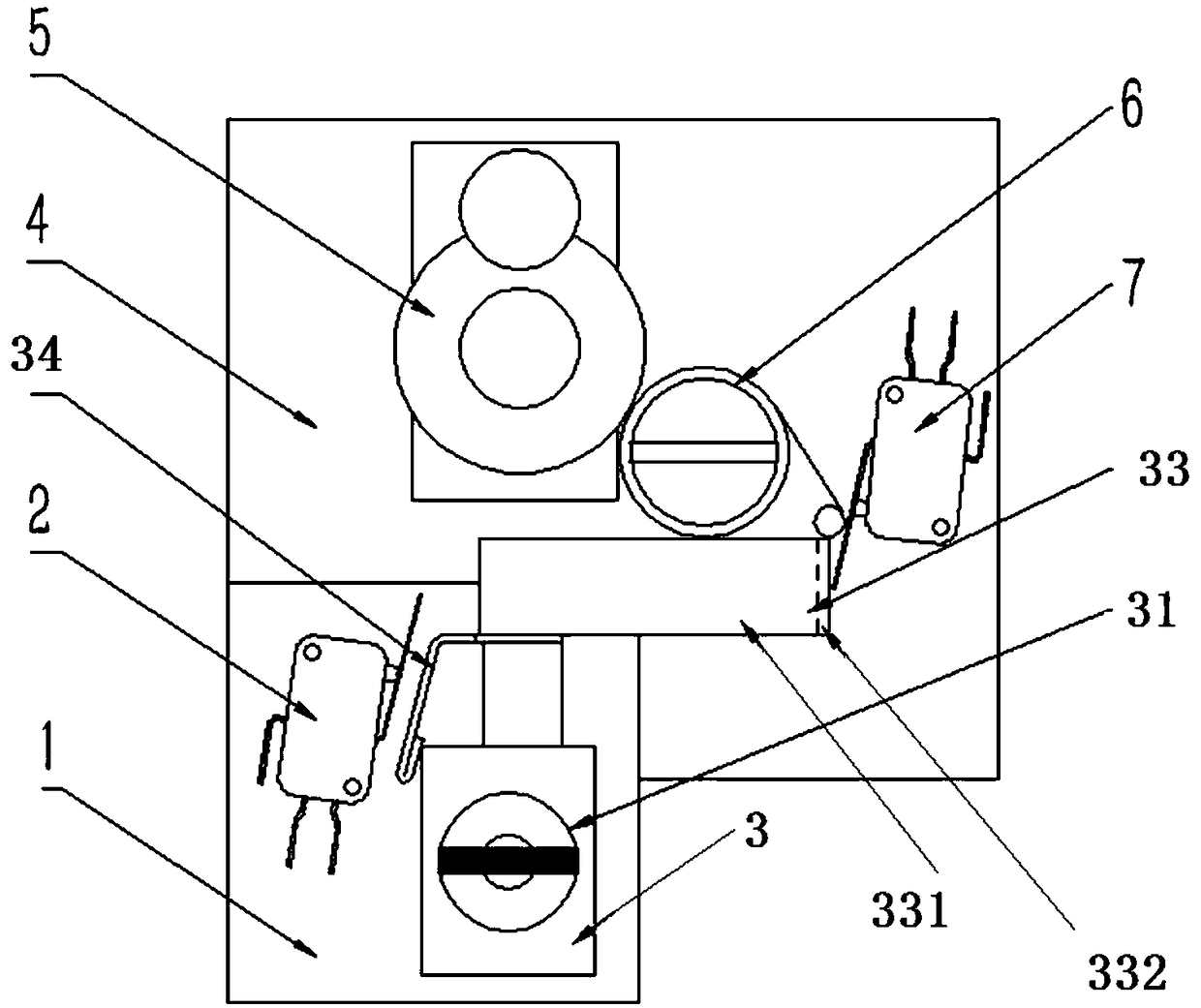
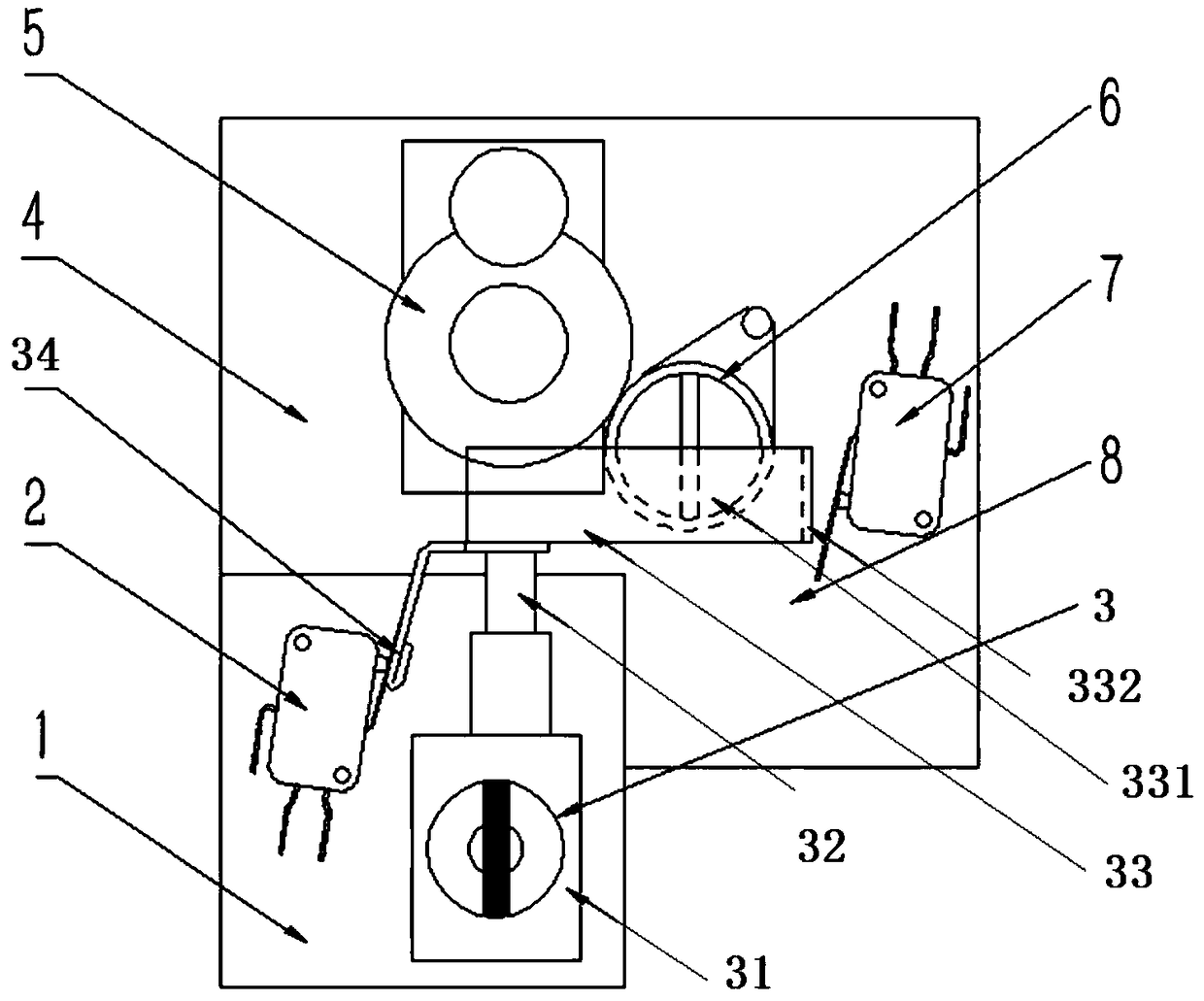
[0024] The specific embodiment of switchgear assembly of the present invention, as figure 1 with figure 2 As shown: the switchgear assembly includes three switchgears, and each of the three switchgears controls the on-off between the corresponding power supply and the power line. The opening and closing of the switchgear can be controlled by manual operation and electrical control circuit. The switch cabinet includes a mounting plate 1, a position detection switch 2, a program lock 3, a switch cabinet substrate 4, a switch cabinet electric mechanism 5, an opening and closing operation shaft 6 and a closing detection switch 7. The in-position detection switch 2 and the program lock 3 are installed on the installation board 1, and the installation board 1, the switch cabinet electric mechanism 5, the opening and closing operation shaft 6 and the closing...


PUM


Abstract

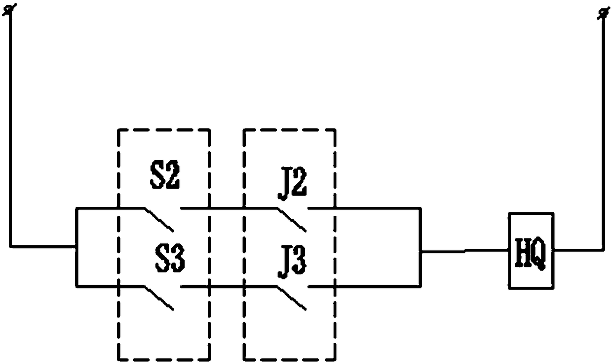
The invention relates to the field of power switch cabinets, and in particular to a switch cabinet assembly and mechanical and electrical interlocking devices thereof. The switch cabinet assembly comprises three switch cabinets with electrical control loops among one another, wherein each switch cabinet comprises a switching-on / off operation shaft and one mechanical and electrical interlocking device; each mechanical and electrical interlocking device is provided with a program lock, the three program locks are configured with two keys, a locking rod of each program lock comprises a shieldingpart and a limiting part, the keys can be pulled out only when the program locks are in an unlocking state, and the program locks can be in the unlocking state only when the switch cabinets are switched off; and each electrical interlocking device further comprises an in-position detecting switch and a switching-off detecting switch, the in-position detecting switch and the switching-off detectingswitch are used for being connected to the corresponding electrical control loop when in use, so as to provide locking rod in-position state signals and switching-on / off operation shaft switching-onstate signals to the electrical control loops. The switch cabinet assembly and the mechanical and electrical interlocking devices thereof solve the problems that mechanisms are damaged or power supplyis affected because mechanical operation and electrical operation are inconsistent when two out of three switch cabinets are interlocked in the prior art.

Description

technical field [0001] The invention relates to the field of electric switch cabinets, in particular to a switch cabinet assembly and a mechanical and electrical interlocking device thereof. Background technique [0002] At present, in the field of electrified equipment, dual power supplies or even multiple power supplies are usually used to ensure that when a fault occurs, the power supply to the load can be switched in time to ensure the safety of the electrical equipment. However, in order to avoid damage to electrical equipment and potential safety hazards caused by the main power supply and the backup power supply supplying power at the same time when the dual power supply enters the line. Generally, interlocking is carried out in switch cabinets using dual power supplies or multiple power supplies to ensure that the voltage supplied to electrical equipment does not exceed the safety voltage of electrical equipment. [0003] The commonly used interlocking mechanism now...

Claims


Application Information

Patent Timeline
IPC IPC(8): H01H9/26
CPCH01H9/26H01H2009/267
Inventor 宋晓生周行师军伟吴小钊李豪刘忠雷李克牛艳红姜丹代海辉
Owner XUJI GRP
Learn More