Time sequence control circuit applied to power supplies

A timing control circuit and timing circuit technology, applied in the field of power supply, can solve the problems of low reliability, increased cost, complex components used in peripheral circuits, etc., and achieve the effect of small size and simple circuit structure

Inactive Publication Date: 2019-03-22
CNGC INST NO 206 OF CHINA ARMS IND GRP
View PDF5 Cites 2 Cited by
  • Summary
  • Abstract
  • Description
  • Claims
  • Application Information

AI Technical Summary

Problems solved by technology

[0003] In the existing power-on sequence control circuit, the peripheral circuit is complicated and many components are used, resulting in increased cost and low reliability

Method used


Image

  • Time sequence control circuit applied to power supplies
  • Time sequence control circuit applied to power supplies

Examples


Embodiment Construction

[0018] Now in conjunction with embodiment, accompanying drawing, the present invention will be further described:

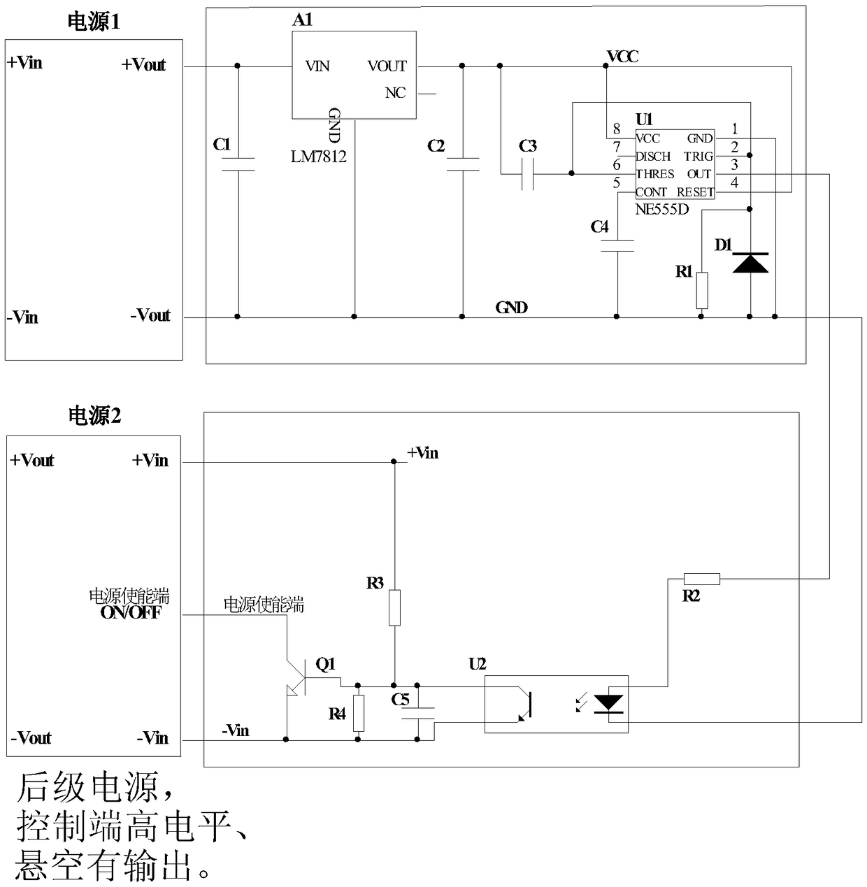
[0019] refer to figure 1 , the invention provides a timing control circuit based on a timing circuit and an enabling circuit, which is applied to a power supply that requires a power-on sequence. The circuit of the present invention can be applied in multiple power supplies that require power-on sequence.

[0020] The timing circuit is connected with the power supply and the enabling circuit.

[0021] The enabling circuit is connected with the timing circuit, and the output of the enabling circuit is connected with the enabling terminal requiring delayed output power supply.

[0022] refer to figure 2 , the structure and principle of each unit circuit of the present invention are described as follows:

[0023] Timing circuit, including but not limited to resistor R1, capacitors C1-C4, three-terminal regulator A1, 555 timer, diode D1. The three-terminal volt...


PUM


Abstract

The invention relates to a time sequence control circuit applied to power supplies. The circuit mainly solves the problem that existing time sequence control circuits are complex. The circuit includesa timing circuit body and an enabling circuit body. A switched-on power supply makes the timing circuit body work normally through a three-terminal voltage regulator; when a time value set by the circuit is reached, a timer outputs high level to trigger the enabling circuit body, and the enabling circuit body controls an enabling end of a delay output power supply for output. The time sequence control circuit is simple in structure and reliable and can be applied to the multi-path power supplies.

Description

technical field [0001] The invention belongs to the technical field of power supplies, and in particular relates to a timing control circuit for power supply applications. Background technique [0002] With the development of electronic technology, there are more and more requirements for power supply for various logic circuits. Many systems expect the power supply to supply power according to a certain power-up sequence. [0003] In the existing power-on sequence control circuit, the peripheral circuit is complicated and many components are used, resulting in increased cost and low reliability. Therefore, a highly practical power-on sequence control circuit is the problem to be solved by the present invention. Contents of the invention [0004] technical problem to be solved [0005] The purpose of the present invention is to avoid the deficiencies of the above-mentioned prior art, and provide a simple, efficient and stable sequential power-on circuit in combination wi...

Claims


Application Information

Patent Timeline
Patent Type & Authority Applications(China)
IPC IPC(8): G05B19/042
CPCG05B19/0423G05B2219/25257
Inventor 贾高松白颖赵飞豹罗强张朋年胡卫华郑昱
Owner CNGC INST NO 206 OF CHINA ARMS IND GRP
Why Eureka
Try Eureka