
Novel array type transient electromagnetic detection system and detection method

A transient electromagnetic, array technology, applied in radio wave measurement systems, electromagnetic/magnetic exploration, measurement devices, etc., can solve the problem that the transmitting coil cannot significantly improve the excitation depth, adverse transient electromagnetic signals, and the excitation field is not uniform problems, to achieve the effect of reducing detection blind spots, reducing costs, and improving quality

Active Publication Date: 2019-03-22
JILIN UNIV
View PDF6 Cites 6 Cited by
  • Summary
  • Abstract
  • Description
  • Claims
  • Application Information

AI Technical Summary

Problems solved by technology

[0002] At present, the traditional ground transient electromagnetic emission system uses a single coil for emission, and there are two main problems: firstly, the excitation field is not uniform enough, the detection size is closely related to the diameter of the coil, and the excitation depth cannot be significantly improved without increasing the diameter of the emission coil
Secondly, the use of a large coil will lead to a large inductance of the coil, which is not conducive to the generation of transient electromagnetic signals

Method used


Image

  • Novel array type transient electromagnetic detection system and detection method
  • Novel array type transient electromagnetic detection system and detection method
  • Novel array type transient electromagnetic detection system and detection method

Examples


Embodiment Construction

[0038] In order to make the object, technical solution and advantages of the present invention clearer, the present invention is further described in detail. It should be understood that the specific embodiments described here are only used to explain the present invention, not to limit the present invention.

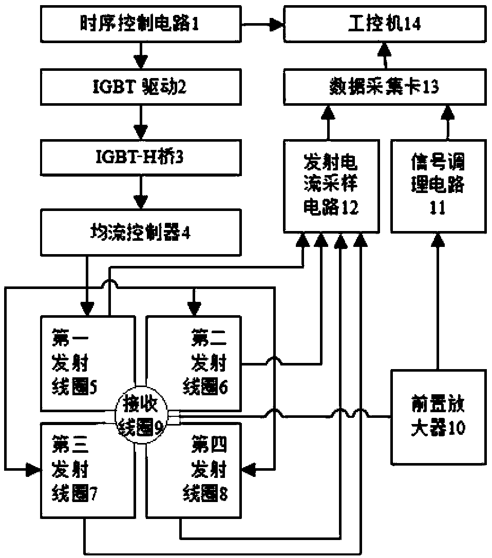
[0039] see figure 1 It shows a schematic block diagram of a novel array type transient electromagnetic detection system according to an embodiment of the present invention; the system includes: a timing control circuit, an IGBT driver, an IGBT-H bridge, a current sharing controller, a first transmitting coil, a second Transmitting coil, third transmitting coil, fourth transmitting coil, current sampling circuit, data acquisition card, receiving coil, preamplifier, signal conditioning circuit, industrial computer.

[0040] Among them, in terms of connection relationship, the timing control circuit 1 is connected to the IGBT-H bridge 3 through the IGBT drive 2, and the I...


PUM

PropertyMeasurementUnit
Diameteraaaaaaaaaa
Side lengthaaaaaaaaaa

Abstract

The invention relates to the technical field of transient electromagnetic underground detection, in particular to a novel array type transient electromagnetic detection system and a detection method.The system comprises a transmitting circuit, a receiving circuit and an industrial computer; the transmitting circuit comprises four transmitting coils arranged in an array, four transmitting coils equally distributing flow directions and a current sharing controller which ensures the same current waveform and amplitude of the four transmitting coils; the receiving circuit includes a receiving coil which is placed on a geometric center of a transmitting coil array and receives a secondary field generated by an excitation magnetic field of the four array type transmitting coils; the industrialcomputer is used for controlling the emission current of the transmitting circuit and controlling the transmitting circuit to evenly distribute the current flowing to the four transmitting coils according to the collected emission current to ensure that the current waveform and the amplitude are consistent. An array type emission method effectively solves the contradiction between the excitation depth and the coil diameter, utilizes the superposition of a plurality of small coils to provide a stronger and more uniform excitation primary field, and is beneficial to improving the quality of a detection signal.

Description

technical field [0001] The invention relates to the technical field of transient electromagnetic underground detection, in particular to a novel array type transient electromagnetic detection system and detection method. Background technique [0002] At present, the traditional ground-based transient electromagnetic emission system uses a single coil for emission, and there are two main problems: firstly, the excitation field is not uniform enough, and the detection size is closely related to the diameter of the coil, and the excitation depth cannot be significantly improved without increasing the diameter of the emission coil. Secondly, the use of a large coil will lead to a large inductance of the coil, which is not conducive to the generation of transient electromagnetic signals. Therefore, it is very meaningful to study the ability to achieve a larger excitation depth with a smaller size, and at the same time reduce the coil inductance to generate a better quality transi...

Claims


Application Information

Patent Timeline
IPC IPC(8): G01V3/10
CPCG01V3/104
Inventor 林婷婷孙德立陈健皮帅张洋
Owner JILIN UNIV
Learn More