Heat pipe type solar heat collector

A solar collector and heat pipe technology, applied in the field of heat collectors, can solve the problems of low degree of intelligence, high temperature, low heat exchange efficiency, etc., so as to improve the heat transfer speed, avoid uneven heating, and meet the absorption capacity. Effect

Active Publication Date: 2019-03-22
菏泽智慧新材料科技有限公司
View PDF6 Cites 5 Cited by
  • Summary
  • Abstract
  • Description
  • Claims
  • Application Information

AI Technical Summary

Problems solved by technology

Current heat collecting tubes are also widely used in the treatment of various diseases, especially in the treatment of chronic diseases caused by aging and old damage to muscles and ligaments, such as CN2167709Y patent, but in the current prior art, such as CN2167709Y patent , because the steam generated directly by heating will cause the temperature of the generated steam to be too high, and it will cause too much moisture in the generated steam, and the drug may be deposited in the lower part because it is a particle, so the active ingredient in the ejected steam The content is too low, and the temperature is too high, and the degree of intelligence in the existing technology is not high, and effective intelligent operation cannot be carried out
[0005] In the background technology, when using solar energy to heat the heat collecting tube, the solar energy either directly heats the heat collecting tube, or generates steam through secondary heat exchange, especially directly heats the heat collecting tube, and uses the convective heat exchange inside the heat collecting tube to carry out the heating of the upper and lower parts of the heat collecting tube. Fluid convection heat exchange, but in this case, the hot fluid in the lower part needs to be naturally convected to the upper part, and the heat transfer efficiency is low

Method used


Image

  • Heat pipe type solar heat collector
  • Heat pipe type solar heat collector
  • Heat pipe type solar heat collector

Examples


Embodiment Construction

[0033] The specific embodiments of the present invention will be described in detail below in conjunction with the accompanying drawings.

[0034] In this article, if there is no special explanation, when it comes to formulas, " / " means division, and "×" and "*" mean multiplication.

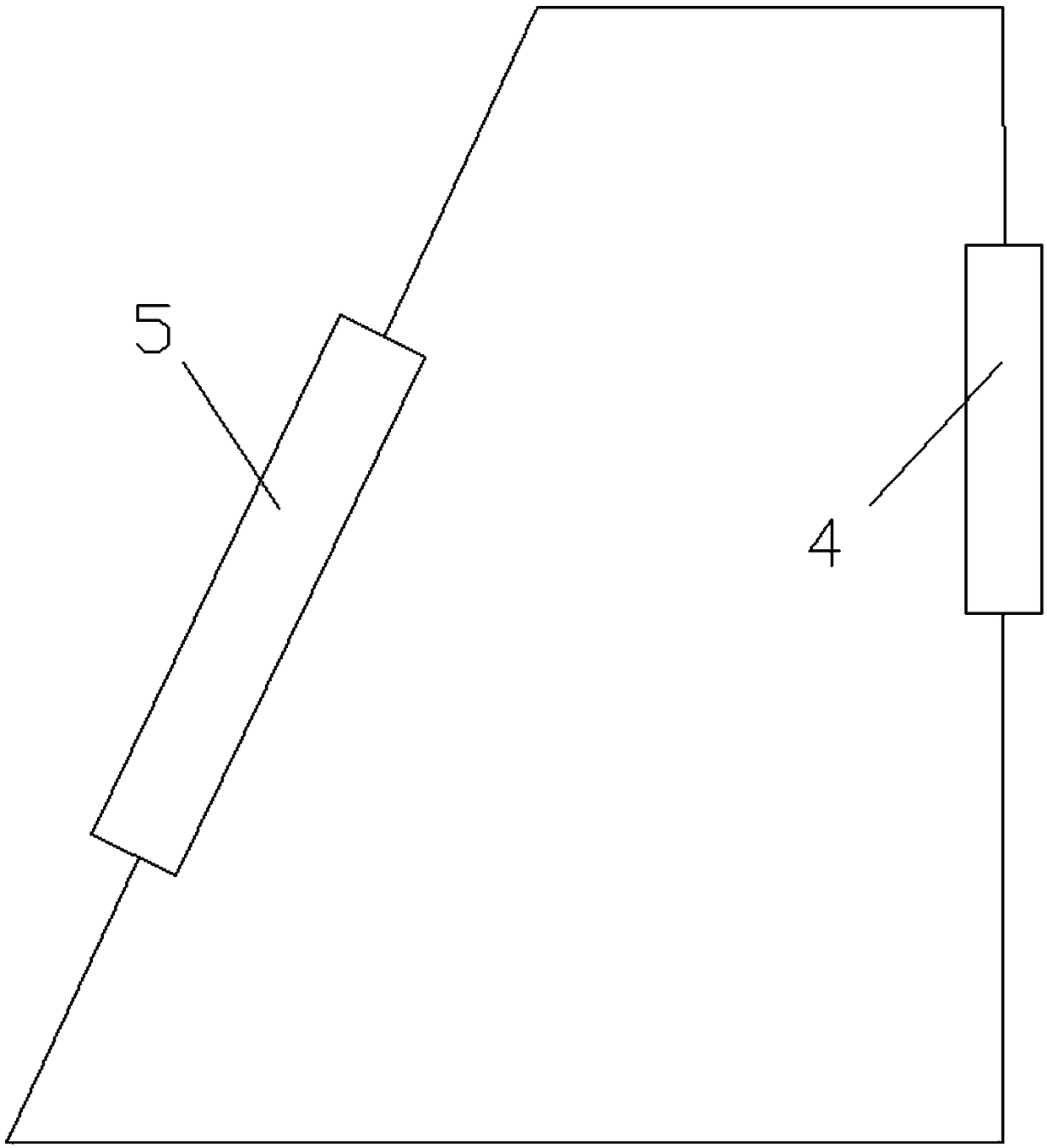
[0035] figure 1 A solar energy system is disclosed, the solar energy system includes a solar heat collector 5 and a heat utilization device 4, the solar heat collector absorbs solar energy, heats a fluid flowing through it, and then the fluid enters the heat utilization device for utilization.

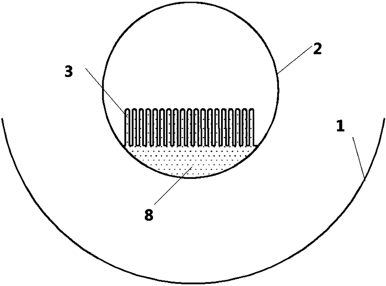
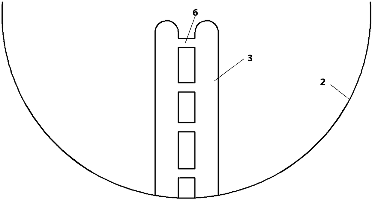
[0036] Such as Figure 2-5 Disclosed is a trough solar heat collector 5 using heat pipes, the heat collector includes a reflector 1 and a heat collection tube 2, the heat collector 2 is located at the focal point of the reflector 1, and the reflector 1 reflects solar energy The heat collecting tube 2 is used to heat the water in the heat collecting tube 2, and the heat collector also includes heat pipe...


PUM


Abstract

The invention provides a heat pipe type solar heat collector. The heat pipe type solar heat collector comprises a reflector and a heat collecting pipe. The heat collecting pipe is located at the focalposition of the reflector, and solar energy is reflected to the heat collecting pipe by the reflector and used for heating water in the heat collecting pipe. A heat pipe is arranged in the heat collecting pipe, and comprises a collecting box and heat dissipating ends, the collecting box is arranged at the bottom of the heat collecting pipe, the heat dissipating ends communicate with the collecting box, the multiple heat dissipating ends stretch upwards from the upper portion of the collecting box, and the bottom of the collecting box is connected to the inner wall of the heat collecting pipe.The novel heat-pipe-structure solar heat collecting pipe is provided, the heat pipe is arranged at the bottom of the heat collecting pipe, by means of the characteristic that the heat transfer speedof the heat pipe is high, the heat transmission speed of the solar energy is increased, and the absorption capacity of heat can be further achieved.

Description

technical field [0001] The invention relates to a heat collecting tube technology, in particular to a heat collecting tube of a heat pipe with a new structure. Background technique [0002] Heat pipe technology was developed in Los Alamos, USA in 1963. national laboratory A heat transfer method called a "heat pipe" invented by George Grover element , it makes full use of the principle of heat conduction and the rapid heat transfer properties of phase change media, and quickly transfers the heat of the heating object to the heat source through the heat pipe, and its thermal conductivity exceeds that of any known metal. [0003] Heat pipe technology was widely used in aerospace, military and other industries before. Since it was introduced into the radiator manufacturing industry, people have changed the traditional radiator design ideas and got rid of the single heat dissipation mode that only relies on high air volume motors to obtain better heat dissipation. The use of h...

Claims


Application Information

Patent Timeline
Patent Type & Authority Applications(China)
IPC IPC(8): F24S10/95F24S23/70F24S80/30
CPCF22B1/006Y02E10/44
Inventor 不公告发明人
Owner 菏泽智慧新材料科技有限公司
Why Eureka
Try Eureka