
Reversing sealing device of low-temperature-resistant combined ring spacer sleeve valve rod forming valve

A sealing device and low-temperature-resistant technology, which is applied in the direction of valve operation/release device, valve device, valve housing structure, etc., can solve the problem of long-time energization of the electromagnetic coil, heat generation, increase in the load of the electromagnetic coil, and increase in the instantaneous resistance of the valve stem and other problems, to achieve the effects of enhancing the sensitivity of the reversing, reducing the running resistance, and solving the reliability of the valve reversing and sealing

Pending Publication Date: 2019-03-22
JINAN FUCHI TECH CO LTD
View PDF0 Cites 2 Cited by
  • Summary
  • Abstract
  • Description
  • Claims
  • Application Information

AI Technical Summary

Problems solved by technology

In order to ensure the sealing performance of the solenoid valve in the existing electromagnetic reversing valve, an O-shaped sealing ring is usually provided on the outer periphery of the valve stem; the sealing performance of the solenoid valve is generally controlled by the interference between the O-shaped sealing ring and the valve stem , in the actual use process, when the interference between the sealing ring and the valve stem is large, the sealing performance of the solenoid valve can be guaranteed, but the instantaneous resistance of the valve stem will increase correspondingly when the solenoid valve changes direction, resulting in a load on the solenoid coil. If the commutation is unsuccessful, the electromagnetic coil will be energized for a long time, generate heat, or even burn out, especially when used in the cold environment in the north; if the interference between the sealing ring and the valve stem is large Hours, the instantaneous reversing resistance of the valve stem will decrease, but it will also cause the problem of the sealing of the reversing valve; in order to solve the contradiction between the instantaneous reversing resistance of the reversing valve stem and the sealing reliability of the sealing ring, we have developed A reversing sealing device for a low temperature resistant combination ring spacer valve stem constitutes a valve

Method used


Image

  • Reversing sealing device of low-temperature-resistant combined ring spacer sleeve valve rod forming valve
  • Reversing sealing device of low-temperature-resistant combined ring spacer sleeve valve rod forming valve
  • Reversing sealing device of low-temperature-resistant combined ring spacer sleeve valve rod forming valve

Examples


Embodiment 1

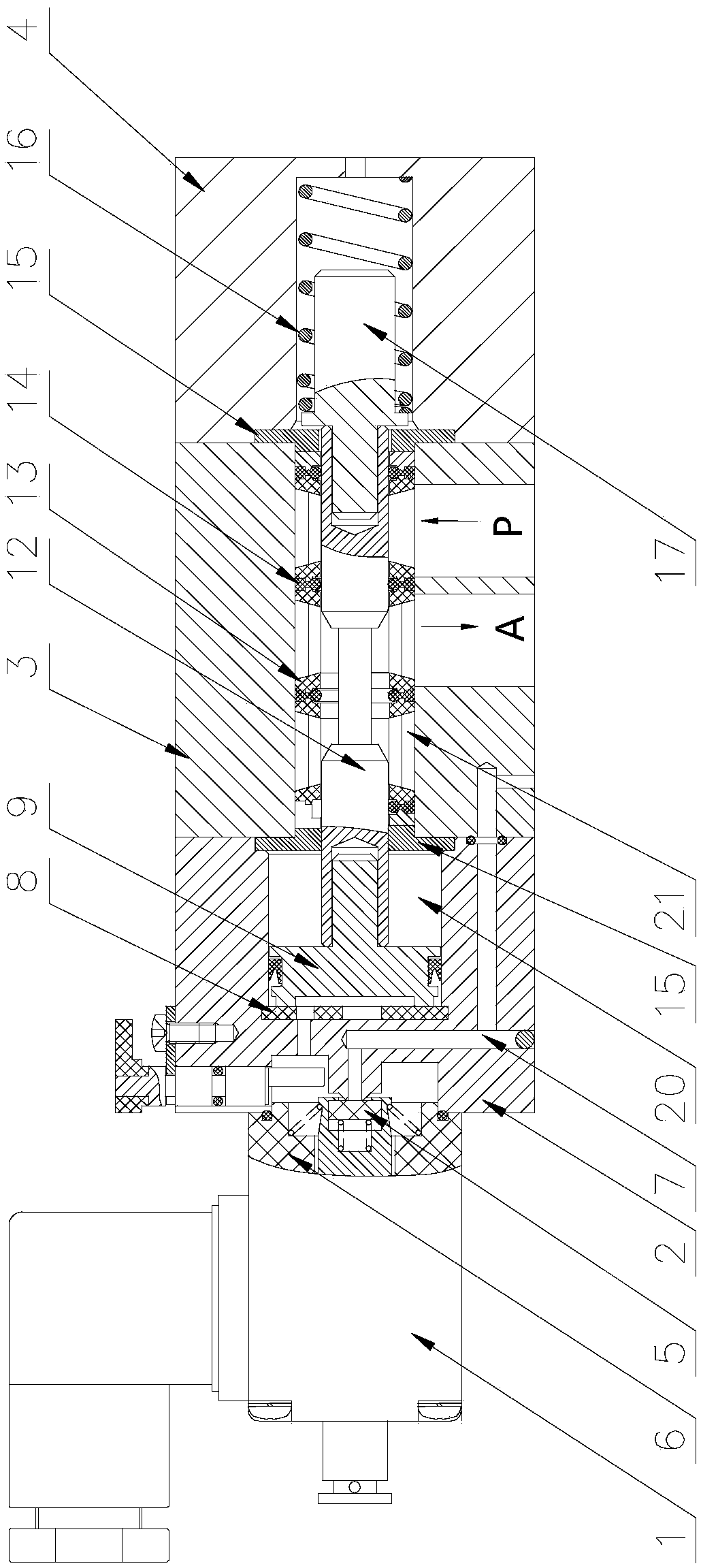
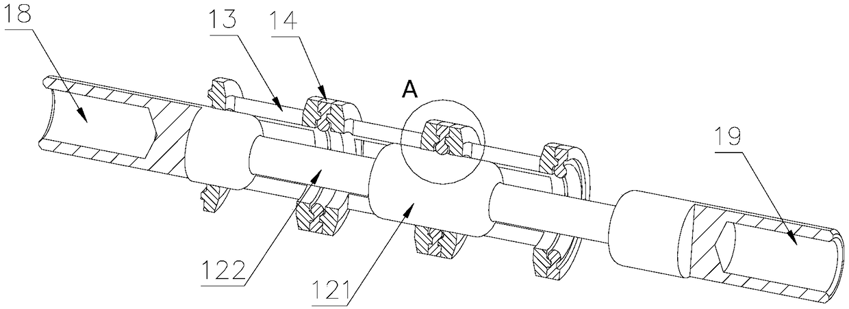
[0039] A valve reversing sealing device composed of a low-temperature resistant combination ring 14 spacer 13 and a valve stem 12, including an electromagnetic pilot valve 1, a valve seat 2, a valve body 3, a valve stem 12, and an end cover 4. One side of the valve seat 2 An electromagnetic pilot valve 1 is provided, and the electromagnetic pilot valve 1 is provided with a movable iron core inside, and the end face 134 of the movable iron core 5 is provided with a gasket, and an electromagnetic coil 6 is wound around the movable iron core; the valve seat 2 One side is provided with an air intake passage 7, and one end of the air intake passage 7 communicates with the outside world, and the other end forms a sealing structure with the gasket of the movable iron core 5; the inside of the valve seat 2 is provided with an air intake chamber 20, the A piston 9 is arranged inside the intake chamber 20, and the section of the piston 9 is an offset T-shape;

[0040] One side of the va...

Embodiment 2

[0055] The difference from Example 1 is that the gap between the end face 134 of the spacer 13 and the lip 143 of the low temperature resistant combination ring 14 is 0.2 mm.

[0056] The included angle between the inner ring of the boss 133 and the end face 134 is 120°, which not only ensures the reversing sensitivity of the valve stem 12 in two directions, but also ensures that the low-temperature resistant combination ring 14 and the valve stem 12 are formed when the lip 143 moves. The tightness between.


PUM


Abstract

The invention discloses a reversing sealing device of a low-temperature-resistant combined ring spacer sleeve valve rod forming valve. An electromagnetic pilot valve is arranged on one side of a valvebase, a piston is arranged inside an air inlet cavity, a valve body is arranged on one side of the valve base, a valve rod is arranged inside a working cavity, and one end of the piston is installedin a first inserting groove; a plurality of spacer sleeves are arranged on one side of the outer part of the valve rod, and a boss is arranged in the middle of one side of the two end surfaces of thespacer sleeves; a low-temperature-resistant combined ring is arranged between every two adjacent spacer sleeves, outer rings and lip edges are integrally formed, grooves matched with the bosses are formed between the outer rings and the lip edges, and one side of a valve body is provided with an end cover. According to the device, two end faces of the low-temperature-resistant combined ring are designed into groove structures correspondingly, and two end faces of the spacer sleeves are designed to be of boss structures; the running resistance at the moment of reversing the valve rod is reduced, meanwhile, the sealing performance of the electromagnetic reversing valve is not reduced after the reversing is completed, then the low-pressure starting and reversing performance of the electromagnetic reversing valve are further reduced, and the electric control reversing performance of the electromagnetic reversing valve is greatly improved.

Description

technical field [0001] The invention belongs to the technical field of electromagnetic reversing valves, and in particular relates to a reversing sealing device for a valve stem constituting a low-temperature resistant combined ring spacer. Background technique [0002] Electromagnetic reversing valve is a control valve that uses the suction force of an electromagnet to push the spool to move to change the direction of fluid flow. It is an automatic basic component used to control fluid. It belongs to the actuator and is not limited to hydraulic and pneumatic. It is used to adjust the direction, flow, speed and other parameters of the medium in the industrial control system. In order to ensure the sealing performance of the solenoid valve in the existing electromagnetic reversing valve, an O-shaped sealing ring is usually provided on the outer periphery of the valve stem; the sealing performance of the solenoid valve is generally controlled by the interference between the O-...

Claims


Application Information

Patent Timeline
Patent Type & Authority Applications(China)
IPC IPC(8): F16K11/07F16K31/40F16K27/04
CPCF16K11/0712F16K27/041F16K31/406
Inventor 尹延慧
Owner JINAN FUCHI TECH CO LTD
Learn More