
Synchronous hydraulic control device

A control device and hydraulic synchronization technology, which is applied in the direction of fluid pressure actuators, servo motors, servo meter circuits, etc., can solve the problems that the production of devices or systems cannot be continued, the accumulation of errors in synchronous motors, and the reduction of synchronization performance, etc., to achieve improvement Operational efficiency and productivity, reduced failure rate, low maintenance rate effect

Pending Publication Date: 2019-03-22
MCC CAPITAL ENGINEERING & RESEARCH
View PDF0 Cites 1 Cited by
  • Summary
  • Abstract
  • Description
  • Claims
  • Application Information

AI Technical Summary

Problems solved by technology

The synchronous motor is the rigid synchronization of the motor speed of each stream. Due to the objective mechanical error and the unevenness of the load, as the use time increases, the synchronous motor will produce accumulated errors, so the error cannot be automatically eliminated by itself.
In addition, as the wear of the motor increases, its synchronous performance will also decrease, but manual intervention cannot be performed, so the production of the controlled device or system will not be able to continue continuously during production and use.
[0003] Although closed-loop control can achieve high synchronization accuracy, it has high requirements for the response of the valve, the accuracy of the valve and the accuracy of the oil, which leads to a high cost
At the same time, the closed-loop control will inevitably use the position sensor, and the protection of the position sensor and its use environment also have higher requirements, and the working conditions of high temperature and humidity will be greatly restricted
In addition, the core component in the closed-loop control is the electrical PLC, but the deadliest component is also the electrical PLC, so once it is powered off or the electrical PLC fails, the entire device will not work

Method used


Image

  • Synchronous hydraulic control device

Examples


Embodiment Construction

[0027] The details of the present invention can be understood more clearly with reference to the accompanying drawings and the description of specific embodiments of the present invention. However, the specific embodiments of the present invention described here are only for the purpose of explaining the present invention, and should not be construed as limiting the present invention in any way. Under the teaching of the present invention, the skilled person can conceive any possible modification based on the present invention, and these should be regarded as belonging to the scope of the present invention. It should be noted that when an element is referred to as being “disposed on” another element, it may be directly on the other element or there may also be an intervening element. When an element is referred to as being "connected to" another element, it can be directly connected to the other element or intervening elements may also be present. The terms "mounted", "connec...


PUM


Abstract

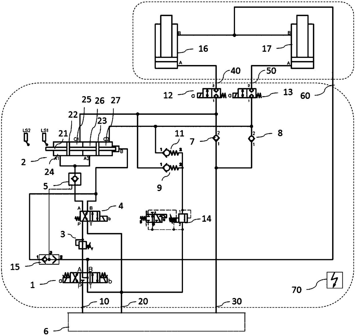
The invention discloses a synchronous hydraulic control device, and relates to the technical field of hydraulic control. The synchronous hydraulic control device comprises a three-position four-way electromagnetic valve, a hydraulic control one-way valve, a two-position four-way electromagnetic valve, a synchronous cylinder, a first valve, a second valve, an electromagnetic relief valve, a first port, a second port, a third port, a fourth port, a fifth port and a six port, wherein the first port, the second port and the third port are used for being connected with a hydraulic source, and the fourth port, the fifth port and the six port are used for being connected with a first driving hydraulic cylinder and the second driving hydraulic cylinder. The synchronous cylinder includes a first cylinder body, a second cylinder body, a movable rod body disposed between the first cylinder and the second cylinder in a penetrating mode, a first piston and a second piston, wherein the first pistonand the second piston are connected to the rod body. The first piston divides the first cylinder body into a first cavity and a second cavity, and the second piston divides the second cylinder body into a third cavity and a fourth cavity. The synchronous hydraulic control device is able to adopt conventional hydraulic components to achieve a multi-cylinder synchronous motion by using simple electrical control.

Description

technical field [0001] The invention relates to the technical field of hydraulic control, in particular to a hydraulic synchronous control device. Background technique [0002] The existing hydraulic synchronization technology generally adopts synchronous motor or closed-loop control. The synchronous motor is a rigid synchronization of the motor speed of each stream. Due to the objective mechanical error and the unevenness of the load, as the use time increases, the synchronous motor will produce accumulated errors, so the error cannot be automatically eliminated by itself. In addition, as the amount of wear of the motor increases, its synchronous performance will also decrease, but manual intervention cannot be performed, so the production of the controlled device or system will not be able to continue during production and use. [0003] Although the closed-loop control can achieve high synchronization accuracy, it has high requirements on the response of the valve, the ac...

Claims


Application Information

Patent Timeline
IPC IPC(8): F15B11/22
CPCF15B11/22F15B2211/71
Inventor 王君平韩柏金代宗岭陈卫强
Owner MCC CAPITAL ENGINEERING & RESEARCH
Learn More